Programmable differential capacitors for equalization circuits

a technology of differential capacitors and equalization circuits, applied in the field of equalization circuits, can solve the problems of low cmrr, data errors, poor common mode signal noise rejection, etc., and achieve the effects of improving signal transition speed and strength, optimizing circuit performance, and common mode noise rejection

Inactive Publication Date: 2005-03-22
ALTERA CORP
View PDF7 Cites 46 Cited by
  • Summary
  • Abstract
  • Description
  • Claims
  • Application Information

AI Technical Summary

Benefits of technology

In accordance with the invention, equalization circuitry is provided that includes programmable differential capacitance. This programmable capacitance allows different values of capacitance to be selectively conductively coupled within an equalization circuit to customize and optimize circuit performance under different conditions and for different applications. A selected value of capacitance determines the degree to which common mode noise rejection and signal transition speed and strength are improved. The programmable capacitance can be provided by varactors or capacitors.

Problems solved by technology

Known equalization circuits, however, may have the disadvantage of relatively poor common mode signal noise rejection, resulting in a low CMRR.
A low CMRR can result in data errors (e.g., a logical 0 being incorrectly interpreted as logical 1 and / or vice versa).
Such errors can adversely affect an entire system.

Method used


Image

  • Programmable differential capacitors for equalization circuits
  • Programmable differential capacitors for equalization circuits
  • Programmable differential capacitors for equalization circuits

Examples


Embodiment Construction

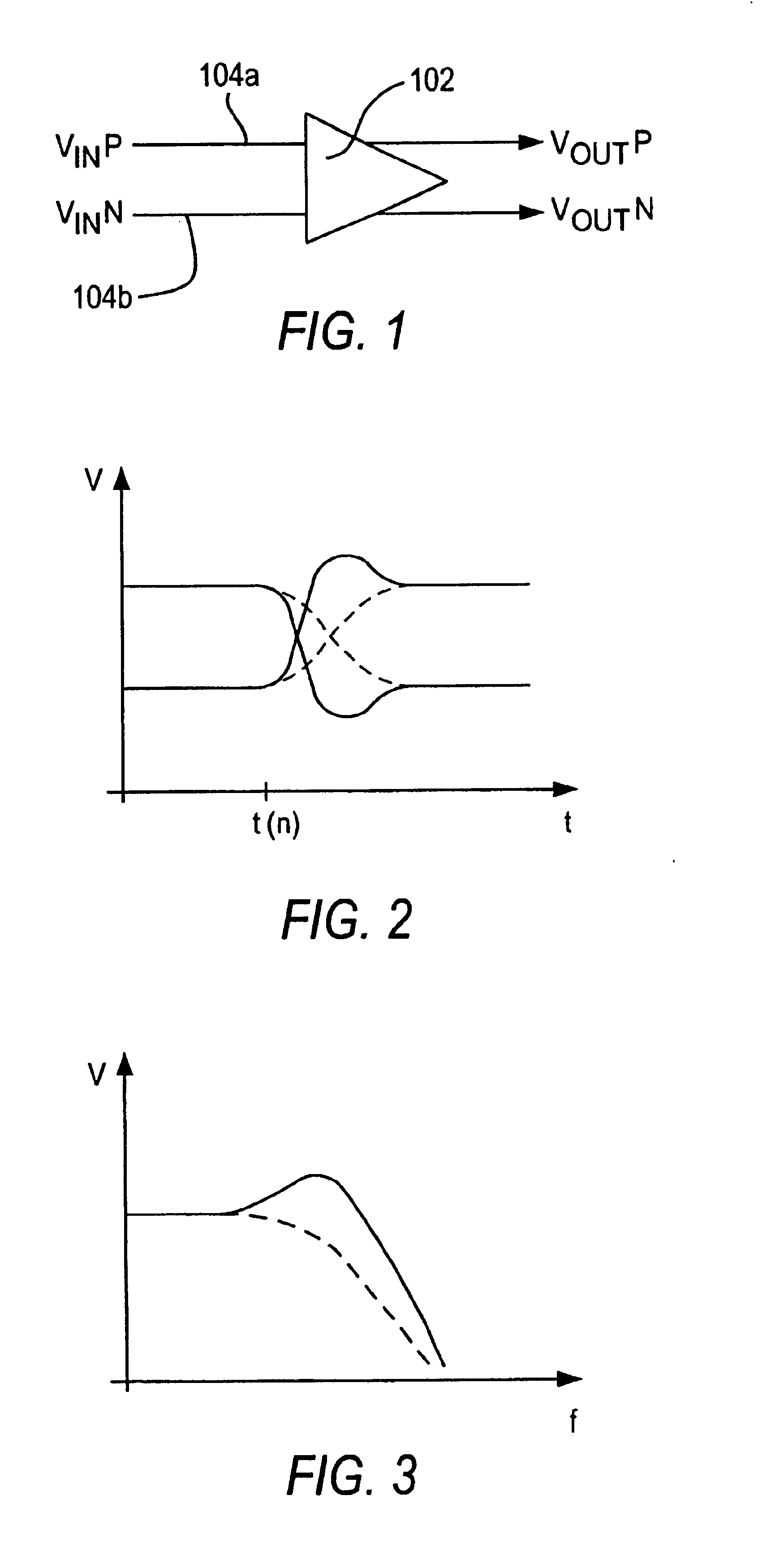
FIG. 1 shows an input driver or buffer 102 typically found in digital data receiver circuits. Driver 102 receives digital data information via a pair of conductors 104a, b (e.g., signal wires)—using differential signaling. As is well known by those skilled in the art, differential signaling typically means that different digital data values (i.e., logical 0 and logical 1) are signaled via conductors 104a, b in accordance with whether the voltage on conductor 104a is higher than the voltage on conductor 104b or vice versa. For example, a logical 1 value may be indicated by the voltage on conductor 104a being higher than the voltage on conductor 104b. A logical 0 value may be indicated by the voltage on conductor 104b being higher than the voltage on conductor 104a. The signals on the two conductors are thus effectively complements of one another. It is typically desired in differential signaling for the average of the voltages on the two conductors to be substantially constant. This ...


PUM


Abstract

Programmable differential capacitance is implemented in equalization circuits. The programmable differential capacitance improves the common mode rejection ratio of circuits processing differential signals of various frequencies and voltage swings. Multiple capacitance devices provide the programmable capacitance, which provides an equalization circuit with different, selectable (i.e., programmable) values of capacitance for boosting the transition speed and strength of differential signals processed by the equalization circuit.

Description

BACKGROUND OF THE INVENTIONThis invention relates to equalization circuits. More particularly, this invention relates to equalization circuits that have programmable differential capacitance to improve performance.Known equalization circuits often employ capacitance devices to improve signal transition speed and strength when responding to the transition of an incoming signal. Equalization circuits are typically used with differential signaling (such as low voltage differential signaling (LVDS) or current mode logic (CML) signaling). Differential signals are pairs of signals that propagate in parallel. Each is usually a logical complement of the other. That is, when one signal is at a high voltage (e.g., a “logical 1”), the other is at a low voltage (e.g., a “logical 0”), and vice versa. The equalization circuit operates on both signals substantially simultaneously.Differential signals (e.g., V1 and V2) can be equivalently thought of as a difference signal (i.e., V1−V2) and a common...

Claims


Application Information

Patent Timeline
Patent Type & Authority Patents(United States)
IPC IPC(8): H03K5/22H04L25/03
CPCH04L25/03878
Inventor MAANGAT, SIMAR
Owner ALTERA CORP
Why Eureka
Try Eureka