Semiconductor chip assembly with chip in substrate cavity

Inactive Publication Date: 2005-04-05
BRIDGE SEMICON
View PDF149 Cites 47 Cited by
  • Summary
  • Abstract
  • Description
  • Claims
  • Application Information

AI Technical Summary

Benefits of technology

An object of the present invention is to provide a semiconductor chip assembly with a chip, a cond

Problems solved by technology

In addition, flip-chip bonding requires minimal mounting area and weight which results in overall cost saving since no extra packaging and less circuit board space are used.
While flip-chip technology has tremendous advantages over wire bonding and TAB, its cost and technical limitations are significant.
For instance, the cost of forming bumps on the pads is significant.
In addition, an adhesive is normally underfilled between the chip and the support circuit to reduce stress on the solder joints due to thermal mismatch between the chip and the support circuit, and the underfilling process increases both manufacturing complexity and cost.
Finally, the solder is typically a tin-lead alloy and lead-based materials are becoming far less popular due to environmental concerns over disposing of toxic materials and leaching of toxic materials into ground water supplies.
Drawbacks to this approach include complicated manufacturing requirements, high cost, and chip loss if the additional circuitry is defective.
In particular, since the chip or wafer provides a substrate for the additional circuitry, chips will be l

Method used


Image

  • Semiconductor chip assembly with chip in substrate cavity
  • Semiconductor chip assembly with chip in substrate cavity
  • Semiconductor chip assembly with chip in substrate cavity

Examples


Embodiment Construction

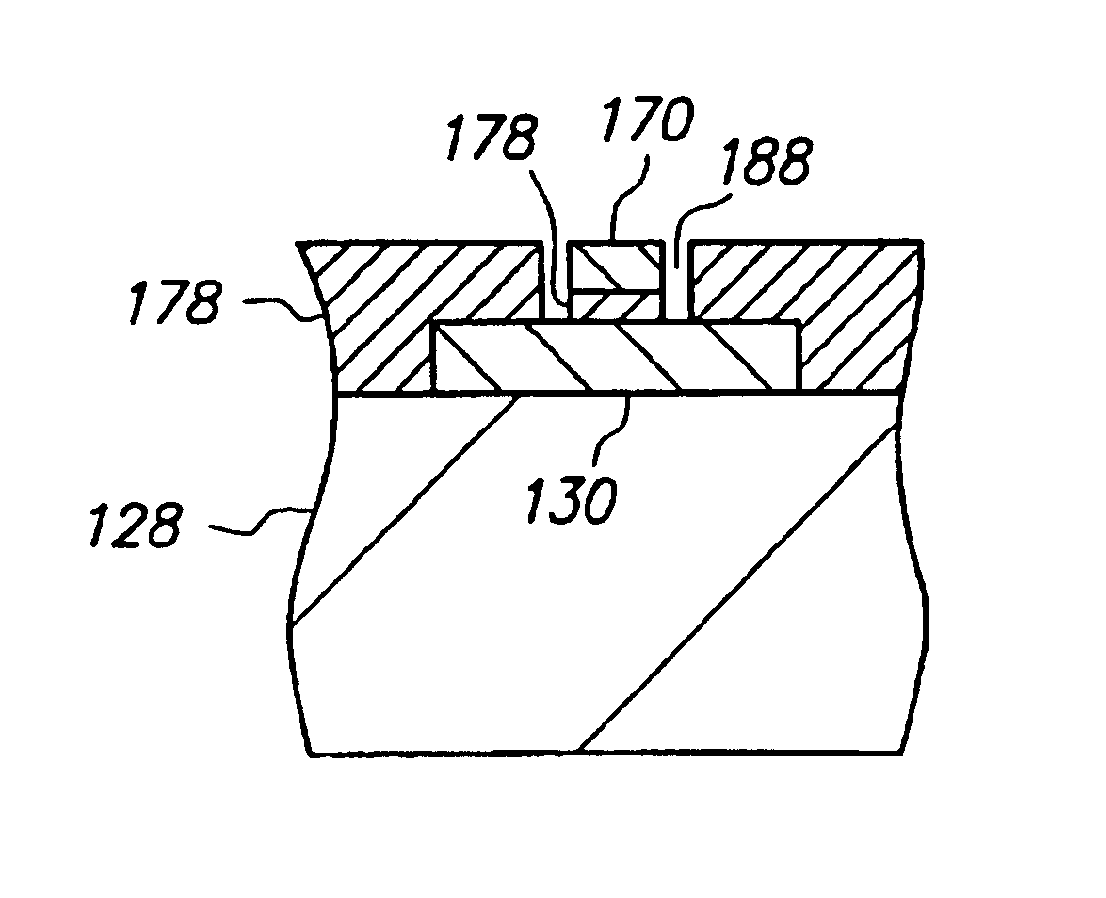
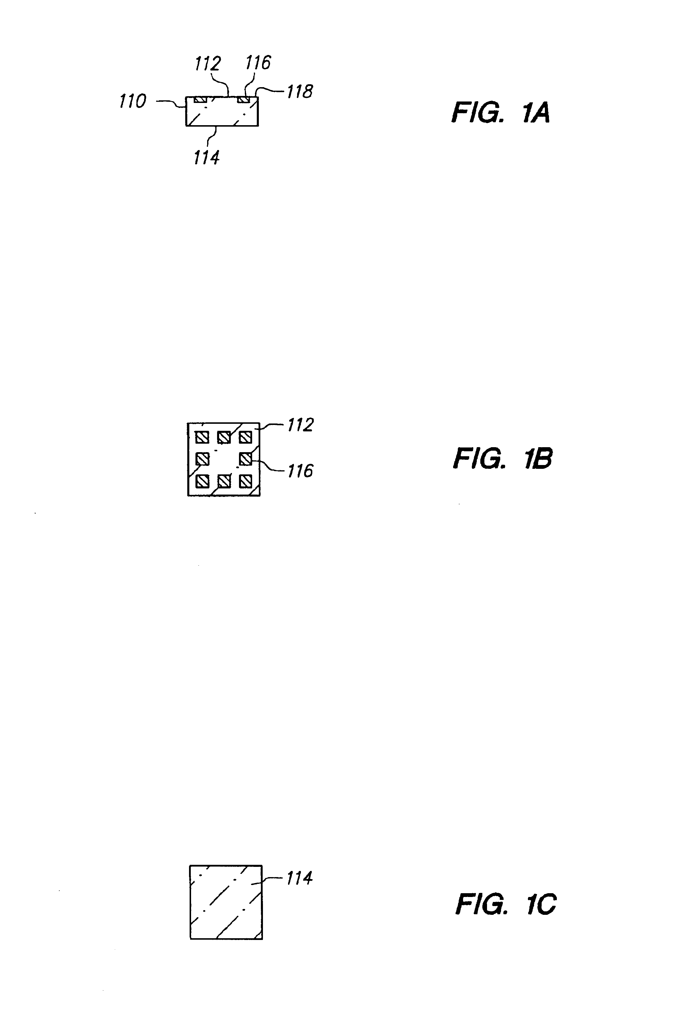
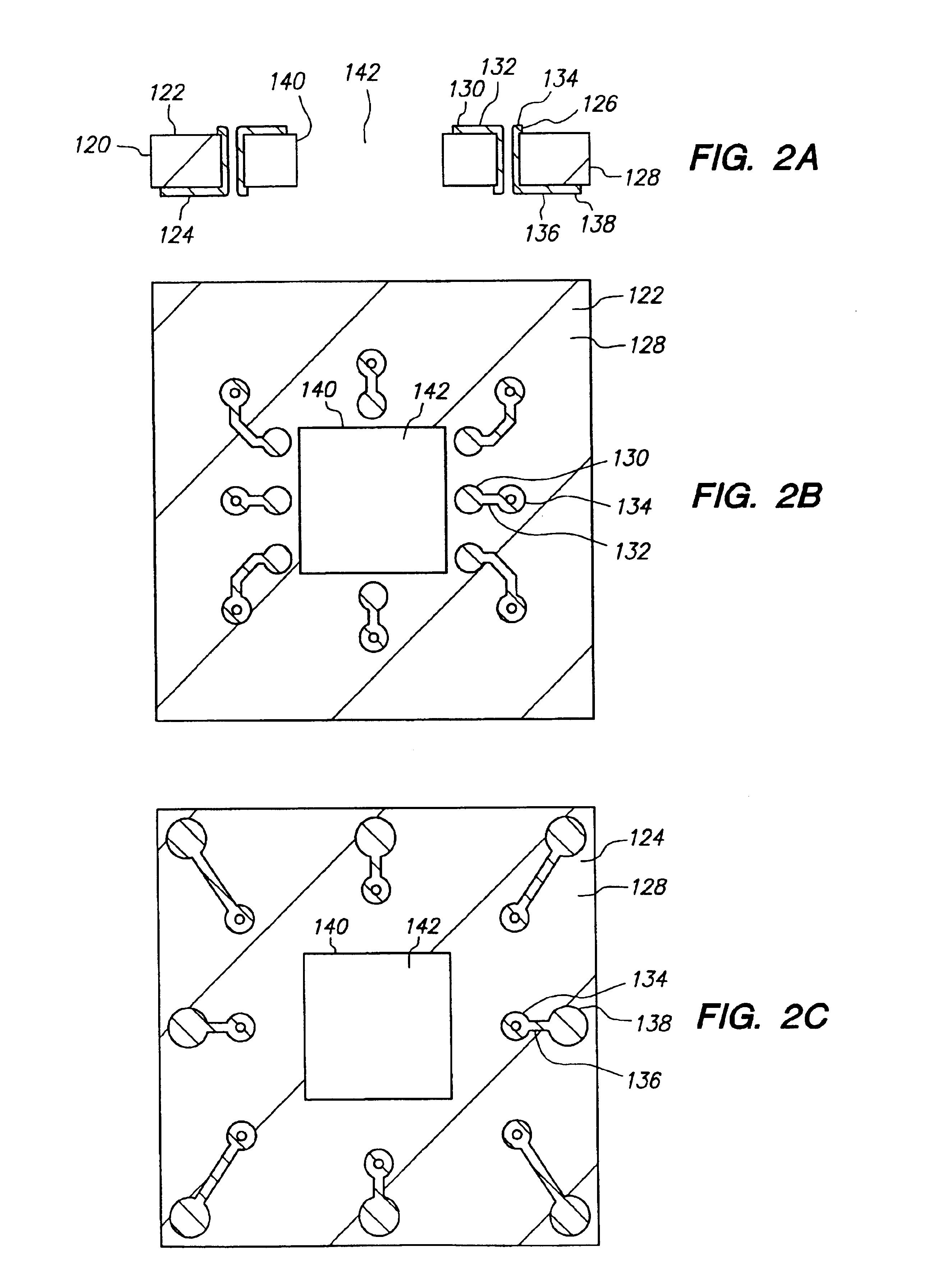
FIGS. 1A-14A, 1B-14B and 1C-14C are cross-sectional, top and bottom views, respectively, of a method of making a semiconductor chip assembly in accordance with a first embodiment of the present invention.

FIGS. 1A, 1B and 1C are cross-sectional, top and bottom views, respectively, of semiconductor chip 110 which is an integrated circuit in which various transistors, circuits, interconnect lines and the like are formed (not shown). Chip 110 includes opposing major surfaces 112 and 114, conductive pad 116 and passivation layer 118. Chip 110 has a length and width across surfaces 112 and 114 of 10 millimeters, and a thickness between surfaces 112 and 114 of 350 microns. Surface 112 is the active surface and includes pad 116 and passivation layer 118.

Pad 116 is substantially aligned with passivation layer 118 so that surface 112 is essentially flat. Alternatively, if desired, pad 116 can extend above or be recessed below passivation layer 118. Pad 116 provides a bonding site to electrica...


PUM


Abstract

A semiconductor chip assembly includes a semiconductor chip that includes first and second opposing major surfaces, wherein the first surface of the chip includes a conductive pad, a substrate that includes first and second opposing major surfaces, wherein the first and second surfaces of the substrate include a conductive terminal and a dielectric base, the conductive terminal extends through the dielectric base to the first and second surfaces of the substrate, a cavity extends from the first surface of the substrate into the substrate, the first surfaces of the chip and the substrate face in a first direction, the second surfaces of the chip and the substrate face in a second direction, and the chip extends into the cavity, a conductive trace in an electrically conductive path between the conductive terminal and the pad, and an adhesive disposed between the conductive trace and the chip, the conductive trace and the substrate, and the chip and the substrate.

Description

BACKGROUND OF THE INVENTION1. Field of the InventionThe present invention relates to a semiconductor chip assembly, and more is particularly to a semiconductor chip assembly that includes a semiconductor chip, a conductive trace and a substrate and its method of manufacture.2. Description of the Related ArtSemiconductor chips have input / output pads that must be connected to external circuitry in order to function as part of an electronic system. The connection media is typically an array of metallic leads (e.g., a lead frame) or a support circuit (e.g., a substrate), although the connection can be made directly to a circuit panel (e.g., a mother board). Several connection techniques are widely used. These include wire bonding, tape automated bonding (TAB) and flip-chip bonding.Wire bonding is by far the most common and economical connection technique. In this approach, wires are bonded, one at a time, from the chip to external circuitry by thermocompression, thermosonic or ultrasoni...

Claims


Application Information

Patent Timeline
IPC IPC(8): H05K3/40H01L21/60H01L23/498H01L23/538
CPCH01L23/49838H01L23/5389H01L24/18H01L24/82H01L2224/1134H01L2224/131H01L2224/18H01L2224/82047H01L2224/83192H01L2224/92144H01L2924/01011H01L2924/01012H01L2924/01013H01L2924/01015H01L2924/01027H01L2924/01029H01L2924/0103H01L2924/0104H01L2924/01046H01L2924/01074H01L2924/01078H01L2924/01079H01L2924/01082H01L2924/01327H01L2924/09701H01L2924/14H01L2924/1433H01L2924/15173H01L2924/19041H01L2924/19043H01L2924/30107H01L2924/3011H01L2924/3025H05K3/4046H01L2924/00013H01L2924/01005H01L2924/01006H01L2924/01019H01L2924/01024H01L2924/01033H01L2924/01047H01L2924/01087H01L2924/014H01L2224/45144H01L2224/45124H01L2224/05624H01L2924/10253H01L2924/00014H01L2224/48624H01L2224/0401H01L2924/00015H01L2224/13099H01L2924/00H01L2224/48H01L2224/48724H01L2924/3511H01L2924/3512H01L21/568H01L2224/04105H01L21/565
Inventor WANG, CHIA-CHUNGLIN, CHARLES W. C.
Owner BRIDGE SEMICON
Why Eureka
Try Eureka