
Advanced hybrid coal gasification cycle utilizing a recycled working fluid

a technology of working fluid and hybrid coal, which is applied in the direction of combined combustion mitigation, steam engine plants, lighting and heating apparatus, etc., can solve the problems of reducing system efficiency, reducing plant efficiency by up to eleven percentage points, and high cost, and achieves efficient generation of electric energy.

Inactive Publication Date: 2005-04-12
FOSTER WHEELER ENERGY CORP
View PDF9 Cites 78 Cited by
  • Summary
  • Abstract
  • Description
  • Claims
  • Application Information

AI Technical Summary

Benefits of technology

My invention provides a simple, hybrid gasification cycle system utilizing recycled working fluid, and a method of using the hybrid gasification cycle system, for efficient generation of electric energy.
My invention also provides a simple, hybrid gasification cycle system utilizing recycled working fluid, and a method of using the hybrid gasification cycle system to eliminate or reduce carbon dioxide emissions to the atmosphere.
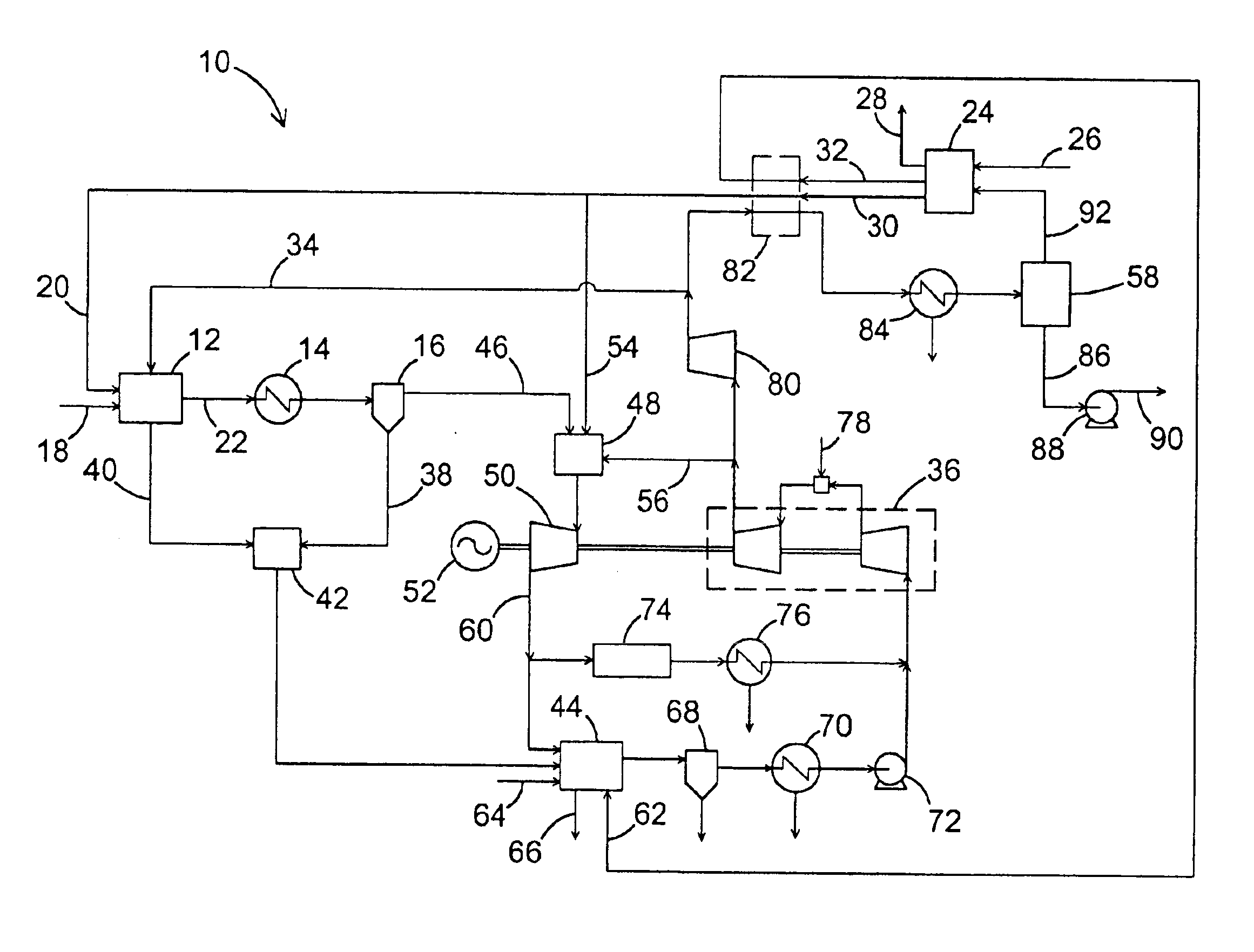
According to one aspect, my invention relates to a power generating system. The power generating system includes a source of fresh, pure oxygen and a gasifier. The gasifier has a solid fuel inlet and a fresh, pure oxygen inlet, and operates at an elevated pressure P1 to convert the solid fuel to syngas, comprising carbon monoxide (CO) and hydrogen (H2), and a solid residue comprising char. A particle separator is arranged in flow connection with the gasifier for separating the char particles from the syngas emanating from the gasifier. A syngas combustor, having a fresh, pure oxygen (O2) inlet and an inlet for syngas discharged from the particle separator, is provided for firing the syngas so as to produce exhaust gas comprising carbon dioxide (CO2), water and excess oxygen. A gas turbine is arranged in flow connection with the syngas combustor, for expanding the exhaust gas so as to generate power with a generator connected to the gas turbine, and discharging expanded exhaust gas through an outlet of the gas turbine. A steam generator is arranged in flow connection with the outlet of the gas turbine, and includes an outlet for discharging processed exhaust gas. A gas compressor system is provided, having an inlet in flow connection with the outlet of the steam generator, and an outlet for discharging a stream of compressed exhaust gas. A first conductor conducts a first portion of the stream of compressed exhaust gas to the gasifier to control the temperature in the gasifier, to provide CO2 and steam for gasification, and to decrease the demand for fresh, pure oxygen therein
According to another aspect, my invention relates to a method of generating power. In the power generating method, fresh, pure oxygen is supplied from an oxygen source. Solid fuel and fresh, pure oxygen are introduced to a gasifier and the solid fuel is converted to syngas, comprising carbon monoxide (CO) and hydrogen (H2), and a solid residue comprising char. Syngas emanating from the gasifier is conducted to a particle separator, and char particles are separated from the syngas in the particle separator. Syngas discharged from the particle separator is fired with fresh, pure oxygen in a syngas combustor, and exhaust gas comprising carbon dioxide (CO2), water and excess oxygen is produced. The exhaust gas is expanded in a gas turbine arranged in flow connection with the syngas combustor, power is generated with a generator connected to the gas turbine, and the expanded exhaust gas is discharged through an outlet of the gas turbine. The expanded exhaust gas from the gas turbine is conducted to a steam generator and processed exhaust gas is discharged through an outlet of the steam generator. The processed exhaust gas from the steam generator is introduced to an inlet of a gas compressor system, and a stream of compressed exhaust gas is produced in the gas compressor system. A first portion of the stream of compressed exhaust gas is conducted to the gasifier, to control the temperature in the gasifier, to provide CO2 and steam for gasification, and to decrease the demand for fresh, pure oxygen therein.

Problems solved by technology

The study revealed that such CO2 removal and / or sequestration systems, when applied to the back end of a pulverized-coal-fired plant, can reduce plant efficiency by up to eleven percentage points with as much as a $30 per ton CO2 removal cost.
This type of a process, however, is energy intensive, costly, and lowers system efficiency due to CO2 regeneration from solvent and the energy losses associated with shifting.
The low-grade heat from the shift reaction contributes to system losses.)
It is estimated that there is an efficiency loss of six percentage points, combined with a CO2 removal cost of $15 per ton, for IGCC plants utilizing such processes.
This process utilizes very complicated equipment, such as a high temperature compressor for the syngas.
The thermal efficiency of this cycle is, however, not very high, since power is generated only by a low efficiency, steam turbine based, Rankine cycle.

Method used


Image

  • Advanced hybrid coal gasification cycle utilizing a recycled working fluid
  • Advanced hybrid coal gasification cycle utilizing a recycled working fluid

Examples


Embodiment Construction

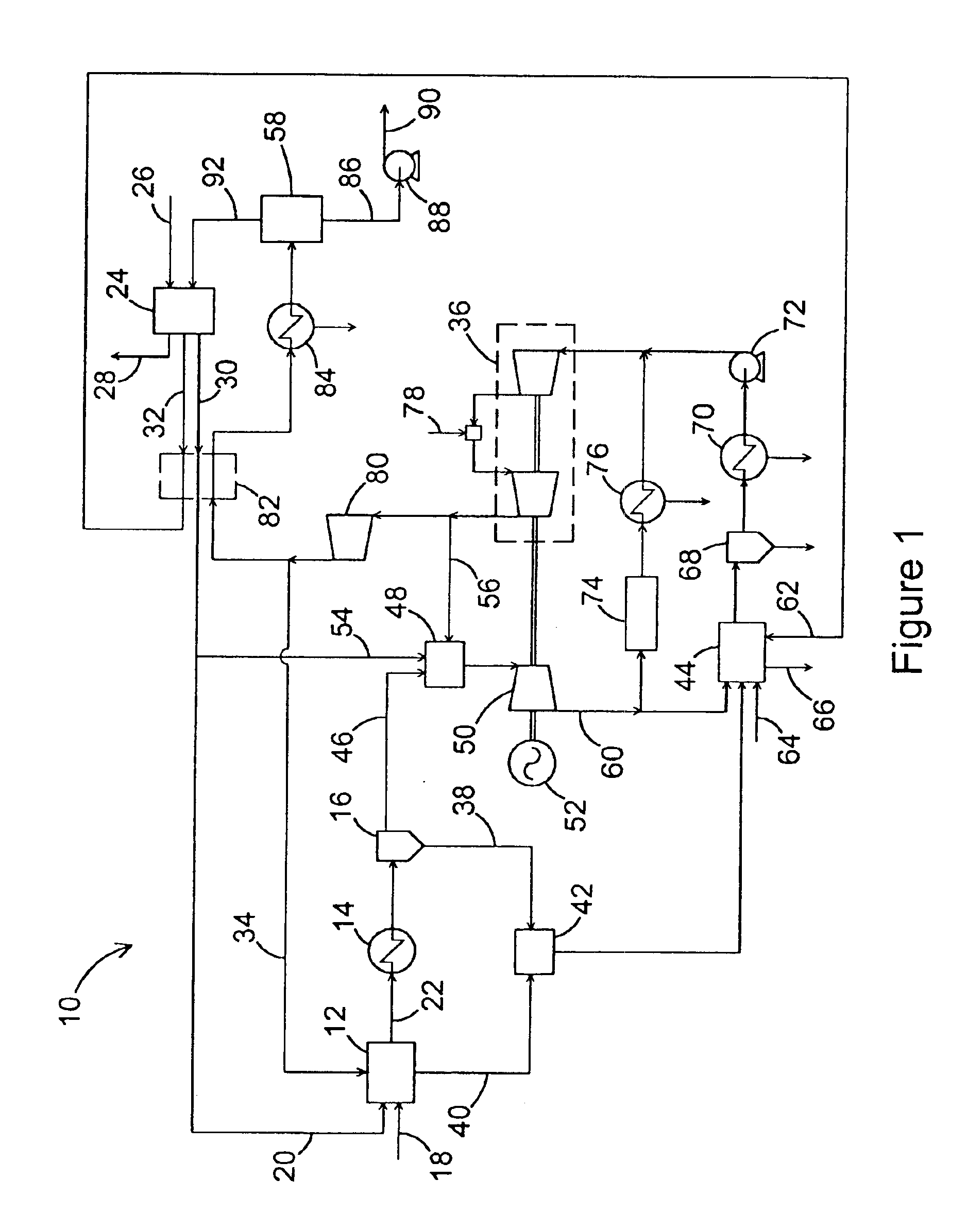
My invention provides an advanced hybrid gasification cycle, in which CO2 is recycled to a gasifier to be used as a gasification reactant and working fluid. One preferred embodiment of my invention is described below, with reference to FIG. 1. A gasifier 12 is preferably a pressurized circulating fluidized bed (PCFB) gasifier operating at a pressure of up to about fifty-five atmospheres, or even higher, for gasifying solid fuel, such as coal. Correspondingly, the gas compressor system, which provides compressed gas comprising mainly carbon dioxide but also some water and oxygen to be recycled to the gasifier 12, increases the pressure of the exhaust gas to a pressure preferably at least as high as the operating pressure of the gasifier 12.

The syngas emanating from the gasifier 12 is preferably cooled in a syngas cooler 14 before char and other solid particles entrained with the syngas are separated in a particle separator 16. The particle separator 16 is preferably a unit of metal c...


PUM


Abstract

A power generating system having a hybrid gasification cycle, in which CO2 is recycled to a gasifier to be used as a gasification reactant and working fluid. The power generating system includes a source of fresh, pure oxygen, a gasifier, a particle separator arranged in flow connection with the gasifier, a syngas combustor, a gas turbine arranged in flow connection with the syngas combustor, a steam generator arranged in flow connection with the outlet of the gas turbine, and a gas compressor system which discharges a stream of compressed exhaust gas. A first portion of the stream of compressed exhaust gas is conducted to the gasifier to control the temperature in the gasifier, to provide CO2 and steam for gasification, and to decrease the demand for fresh, pure oxygen therein.

Description

FIELD OF THE INVENTIONMy invention relates to a hybrid gasification cycle utilizing recycled working fluid, and a method of operating such a system, for generating electrical energy.BACKGROUND OF THE INVENTIONThe relationship between global climate change and the emission of greenhouse gases, such as carbon dioxide (CO2), is well documented. Conventional fossil fuel combusting power plants, such as pulverized-coal-fired power plants, generate significant amounts of CO2. Therefore, there is a seemingly constant drive to improve the efficiency of such power plants and to develop improved technologies to reduce their CO2 emissions. One of the main solutions developed to achieve these goals is based on gasifying coal in a gasifier to generate syngas, which is combusted in a downstream combustor.A recently published study by M. De Lallo, et al., “Evaluation of Innovative Fossil Cycles Incorporating CO2 Removal,” which was presented at the 2000 Gasification Technologies Conference in San ...

Claims


Application Information

Patent Timeline
IPC IPC(8): F01K23/06F01K1/00F02C3/34
CPCF01K23/068F02C3/34Y02E20/18Y02E20/34F25J2215/54F25J2210/50F25J2260/80F25J3/04533F25J3/04545
Inventor FAN, ZHEN
Owner FOSTER WHEELER ENERGY CORP
Learn More