Router line card protection using one-for-N redundancy

Inactive Publication Date: 2005-04-12
BROCADE COMMUNICATIONS SYSTEMS
View PDF20 Cites 131 Cited by
  • Summary
  • Abstract
  • Description
  • Claims
  • Application Information

AI Technical Summary

Benefits of technology

The present invention is directed to a system and method which partition the router line cards, thereby separating the packet forwarding functions from the physical port interfaces or facility modules and also separating the packet forwarding functions from any internal router fabric interfaces. This enables multiple line cards to access any particular set of external facility or internal fabric paths. A method in accordance with the present invention further provides data and control paths that allow any failed working line card within a protection group to be switchably replaced by another line card, which is provided exclusively for protection purposes within the protection group. In particular, a serial bus structure on the port side of a line card allows any optical port within a given protection group to access the protection line card for that group. Incremental excess capacity across the router fabric is provided, so that the protection line card can request and receive grants to transmit packets to the fabric. Logical mapping of line card addressing and identification is used, such that a protection switch of a line card is managed locally and is transparent to other line cards in the router and to all external peer routers.
A benefit of this approach is that one for N protection ratios of the line cards, where N is some integer greater than two, can be achieved, which are very economical, yet provide sufficient system and network availability with acceptable protection switch time performance. An attractive protection switch time is generally any time under 100 milliseconds.

Problems solved by technology

Internet protocol (IP) routers are not protected from line card failures with hot standby immediate acting protection mechanisms.
This mode of protection is slow and is cumbersome to engineer and administer.
A particular problem is that, in the event of failures of line cards or packet forwarding elements, it is impossible to limit the effects of those failures to the router in which the failure occurs.
This approach, however is economically unattractive, in that it consumes multiple switch fabric ports, thus doubling the required port count of the switch fabric.
This results inevitably in underutilizing any particular line card.
Without fast acting hot standby protection, a network must be engineered with duplex and multiple routers and with less than fully utilized traffic capacity on each port.
Then in the event of a facility or port failure during operation, all traffic must be redirected from the failed port to another port, which is available but underutilized and which has enough intrinsic capacity to carry the additional traffic under such a failure circumstance.
The first problem is not what happens once the failure occurs, but the way the network must be engineered to provide this complex protection structure.
This increases the cost not only of the equipment, but of the router itself that now includes redundancy, software costs relating to the intervening network capacity, fiber optic transmission capacity including increased overhead traffic between routers, and administrative and engineering effort.
Failure of a cable at a router can in fact propagate significantly far through a network, resulting in substantial confusion to the network as it adjusts to reconfigured routing.
Thus, small localized failures produce impacts that ripple out through the network, even though their original cause may not have been significant.
In situations where outages occur from time to time, this can become overwhelming to a network.
Even in the best case, the time to perform a repair and restore the original configuration can cause network traffic to slow dramatically.
Again, this affects the capacity of a network, which in the initial stage would have to be engineered for higher capacity than would otherwise be necessary.
A common problem is an intermittent fault in a network, coming into and going out of service repetitively, thereby causing the generation of rerouting messages almost continuously through the network, known in the industry as “route-flap,” resulting in much non-useful traffic.

Method used


Image

  • Router line card protection using one-for-N redundancy
  • Router line card protection using one-for-N redundancy
  • Router line card protection using one-for-N redundancy

Examples


Embodiment Construction

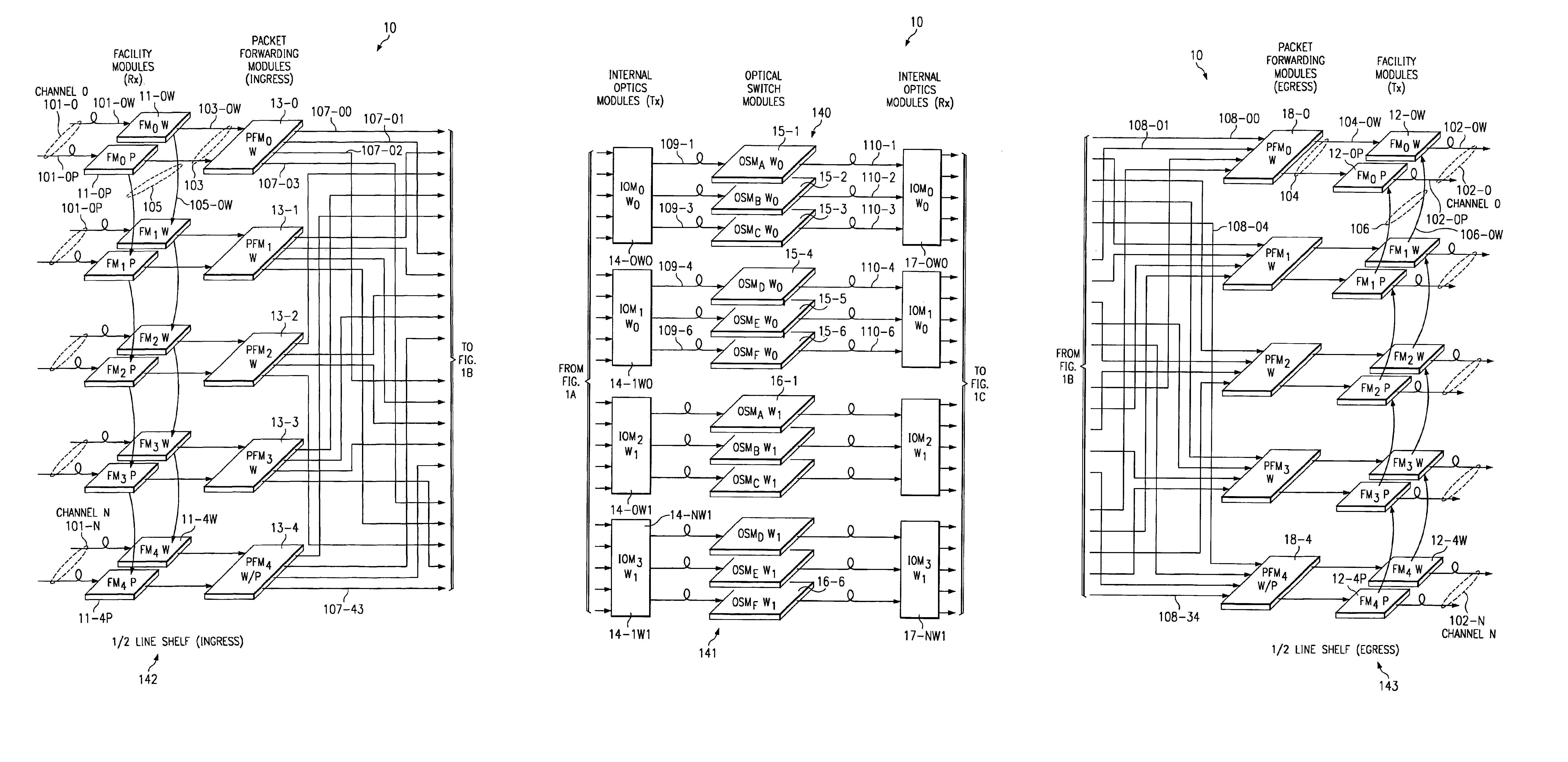
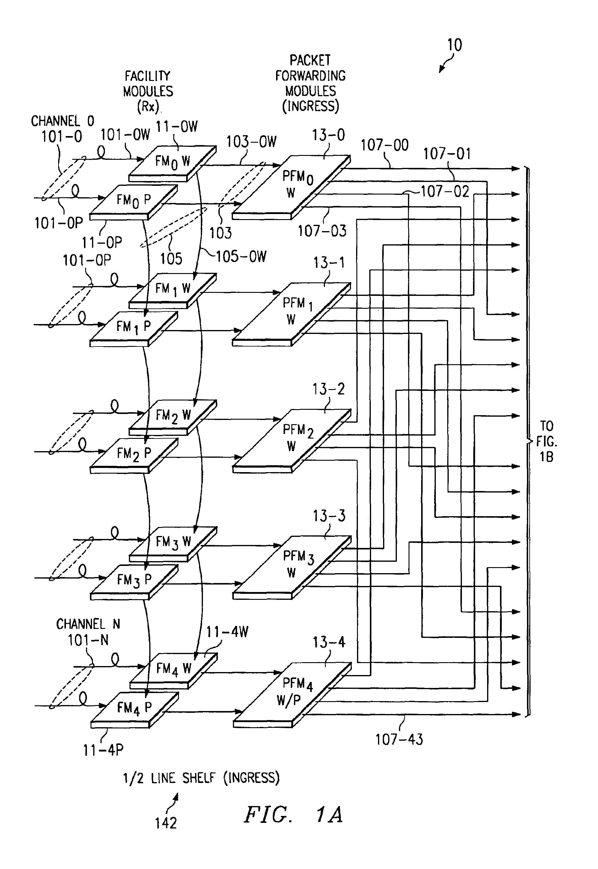
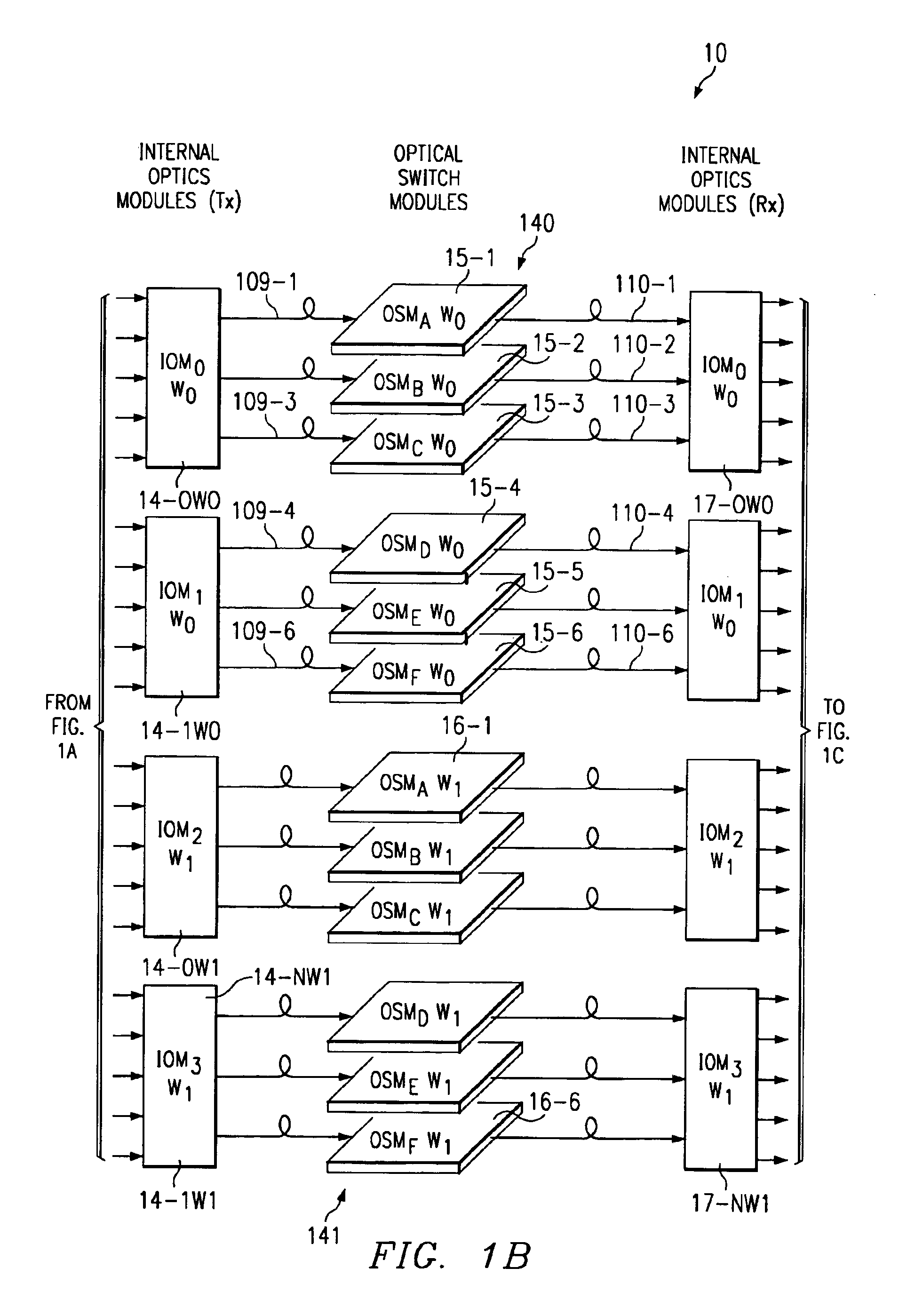
FIGS. 1A-1C form a schematic diagram showing an overview of the data paths through a router 10, in an embodiment of the present invention. For ease of understanding, FIGS. 1A-1C are partitioned into three sequentially adjacent panels. FIGS. 1A-1C do not show how router system 10 is wired, but simply illustrates the flow of data. At the upper left portion of FIG. 1A, an input 101-0 is a first SONET data channel, formatted as Packet-over-SONET in the present embodiment. Input 101-0 includes two optical fibers, namely a working input fiber 101-0W and a protect input fiber 101-0P. Fibers 101-0W, 101-0P carry duplicated information into router 10 from a peer source equipment e.g., another router or piece of SONET transmission equipment, compatible with the Packet-over-SONET format. Protect and working facility module cards 11-0P and 11-0W independently receive duplicate input from respective optic fibers 101-0P and 101-0W and perform an integrity check on the information by computing SON...


PUM


Abstract

Router line cards are partitioned, separating packet forwarding from external or internal interfaces and enabling multiple line cards to access any set of external or internal data paths. Any failed working line card can be switchably replaced by another line card. In particular, a serial bus structure on the interface side interconnects any interface port within a protection group with a protect line card for that group. Incremental capacity allows the protect line card to perform packet forward functions. Logical mapping of line card addressing and identification provides locally managed protection switching of a line card that is transparent to other router line cards and to all peer routers. One-for-N protection ratios, where N is some integer greater than two, can be achieved economically, yet provide sufficient capacity with acceptable protection switch time under 100 milliseconds. Alternatively, protect line cards can routinely carry low priority traffic that is interruptible, allowing the protect line card to handle higher priority traffic previously carried by a failed working line card. This approach renders unnecessary engineering a network for less than full capacity to allow rerouting in the event of individual line card failure. Consequently, all data paths can be fully utilized. If a particular interface module on one data bus needs removal for maintenance, a duplicate data bus is available intact, allowing hot replacement of any working or protect interface module, even while a line card protection switch is in effect.

Description

TECHNICAL FIELDThis application relates to the field of optical communication networks, and particularly to large-scale routers for optical communication networks.BACKGROUNDRouters form a central part of a data communication network and perform general routing. There can be multiple routers in a network. Information typically travels from one router to the next router, and eventually reaches the destination edge of the network. A destination edge router receives the information and decides where it goes from there. Typically it goes to an Internet service provider at the opposite edge of the edge router. If the destination is a household PC, the Internet service provider then sends the information to the destination computer. If there is corporate access to the network, the information may go from the edge router directly to a corporate site.A fabric is a collection of devices which cooperatively provides a general routing capability. Internet protocol (IP) routers require protectio...

Claims


Application Information

Patent Timeline
IPC IPC(8): H04L12/56
CPCH04L45/00H04L49/552H04L45/583H04L45/28
Inventor BLACKMON, HARRY C.BREWER, TONY M.DOZIER, HAROLD W.KLEINER, JIMMCDERMOTT, III, THOMAS C.PALMER, GREGORY S.SHAW, KEITH W.TRAYLOR, DAVID
Owner BROCADE COMMUNICATIONS SYSTEMS
Why Eureka
Try Eureka