Rotor for rotary electric rotor

a technology of electric rotor and rotor core, which is applied in the direction of stator/rotor body manufacturing, magnetic circuit rotating parts, and shape/form/construction of magnetic circuits, etc., can solve the problems of increased irregular output of the rotor, reduced strength of the magnetic pole itself, and reduced strength of the magnetic pole. , to achieve the effect of reducing wind splitting noise, preventing disintegration and deformation of the magnetic pole portion, and increasing the strength of the magnetic pol

Active Publication Date: 2005-04-19
MITSUBISHI ELECTRIC CORP
View PDF9 Cites 12 Cited by
  • Summary
  • Abstract
  • Description
  • Claims
  • Application Information

AI Technical Summary

Benefits of technology

[0008]The present invention aims to solve the above problems and an object of the present invention is to provide a rotor for a rotary electric rotor enabling disintegration and deformation of a magnetic pole portion to be prevented and increases in magnetic resistance resulting from layers of air inside a core to be suppressed by adapting a core shape and preparing a rotor core having smooth outer peripheral surfaces as a solid body to increase strength in the magnetic pole portion while reducing wind-splitting noise.
[0010]Therefore, disintegration and deformation of the magnetic pole portion are prevented by increasing strength in the magnetic pole portion while reducing wind-splitting noise, and increases in magnetic resistance resulting from layers of air inside the core is suppressed.

Problems solved by technology

However, in conventional rotors for rotary electric machines, because the rotor core is constructed by laminating steel plates, the strength of the magnetic poles themselves is reduced.
Thus, the magnetic poles may disintegrate during high-speed rotation of the rotor, or stresses may occur in a magnetic pole portion during an assembly process in which a rotating shaft is pressed into the rotor core, deforming the magnetic poles themselves, etc.
This deformation of the magnetic poles themselves brings about deterioration in dimensional precision, leading to increased irregularities in output from the rotor.
When layers of air form between the laminated steel plates, magnetic resistance is increased, making output deteriorate.

Method used


Image

  • Rotor for rotary electric rotor
  • Rotor for rotary electric rotor
  • Rotor for rotary electric rotor

Examples


embodiment 1

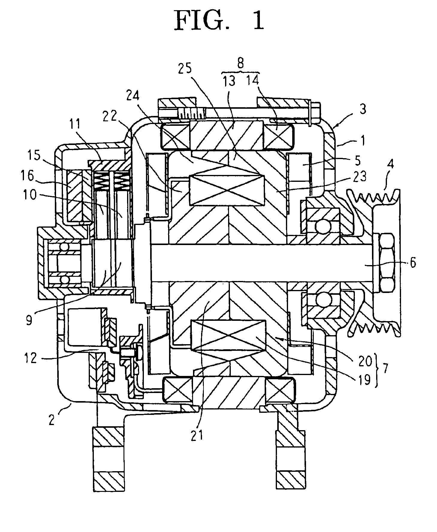
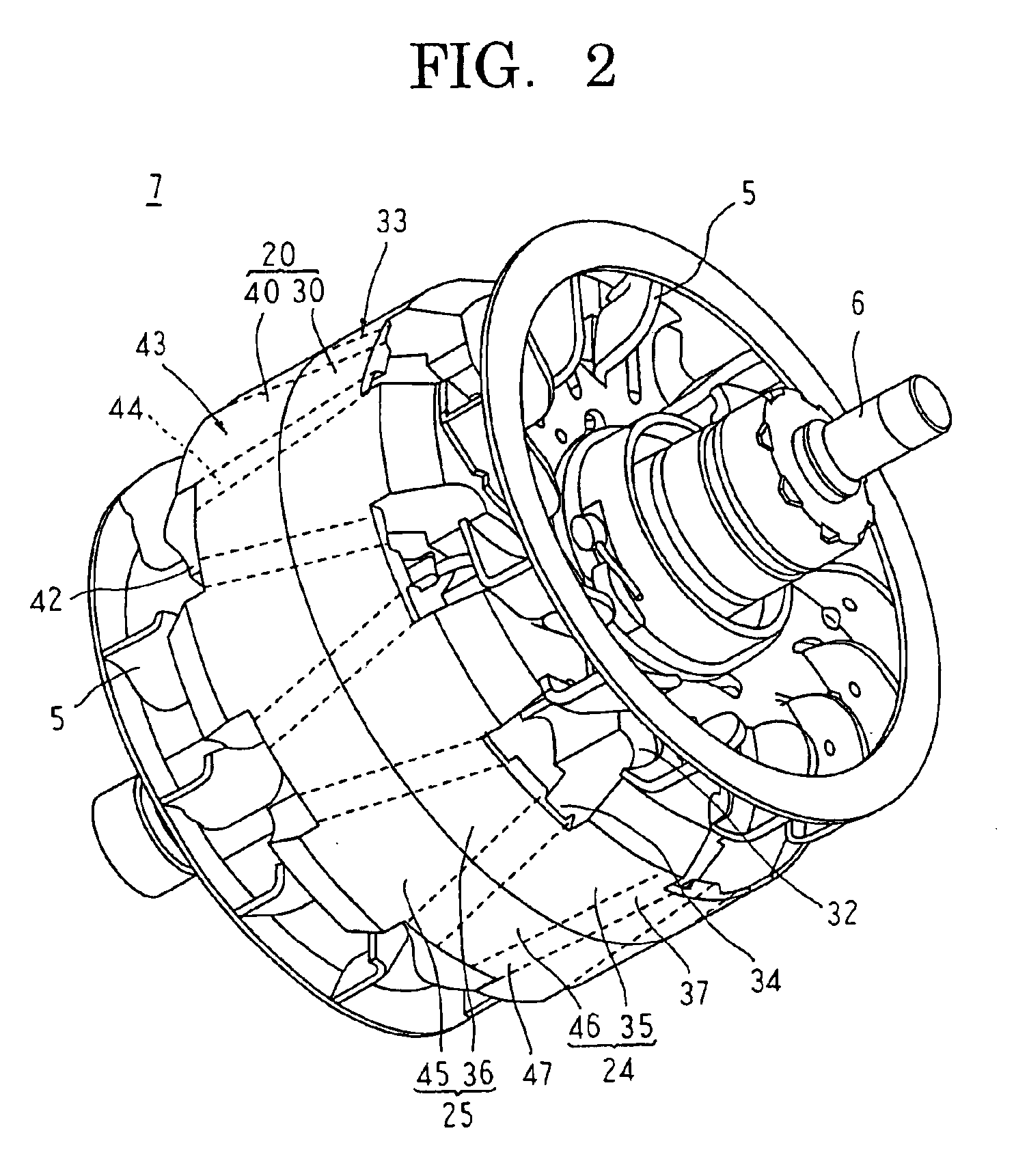
[0026]FIG. 1 is a longitudinal section showing an automotive alternator according to Embodiment 1 of the present invention, FIG. 2 is a perspective showing a rotor of the automotive alternator according to Embodiment 1 of the present invention, FIG. 3 is a front elevation showing a divided core of the rotor of the automotive alternator according to Embodiment 1 of the present invention viewed from a side near a dividing surface, and FIG. 4 is a cross section taken along line IV—IV in FIG. 3 viewed in the direction of the arrows. Moreover, in FIG. 4, a first core division is indicated by broken lines to facilitate explanation.

[0027]In FIG. 1, an automotive alternator functioning as a dynamoelectric machine is provided with: a case 3 constituted by a front bracket 1 and a rear bracket 2 made of aluminum; a shaft 6 disposed inside the case 3, a pulley 4 being secured to a first end portion of the shaft 6; a rotor 7 secured to the shaft 6; fans 5 secured to first and second axial end po...

embodiment 2

[0043]FIG. 5 is a perspective showing a rotor of an automotive alternator according to Embodiment 2 of the present invention, and FIG. 6 is a longitudinal section showing a rotor core of the rotor of the automotive alternator according to Embodiment 2 of the present invention.

[0044]In FIGS. 5 and 6, a rotor core 20A is constructed so as to be divided into a cylindrical portion 51, first and second yoke portions 52 and 53, and a cylindrical magnetic pole portion 54, each prepared as a solid body of a magnetic material such as iron, etc. Recessed grooves 55 having a groove direction lying in an axial direction are recessed into an inner peripheral surface of the cylindrical magnetic pole portion 54 at a uniform angular pitch in a circumferential direction, and claw-shaped magnetic poles 56 are formed so as to be arranged at a uniform angular pitch in a circumferential direction. These claw-shaped magnetic poles 56 are separated on an inner peripheral side by the recessed grooves 55, a...

embodiment 3

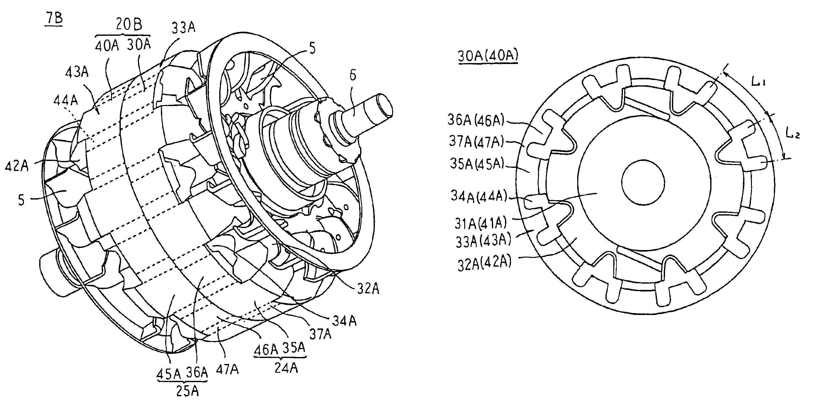
[0051]FIG. 7 is a perspective showing a rotor of an automotive alternator according to Embodiment 3 of the present invention, and FIG. 8 is a front elevation showing a divided core of the rotor of the automotive alternator according to Embodiment 3 of the present invention viewed from a side near a dividing surface.

[0052]In FIGS. 7 and 8, a rotor core 20B is divided at a central position in an axial direction into two sections constituted by first and second core divisions 30A and 40A.

[0053]The first core division 30A is prepared as a solid body of a magnetic material such as iron, etc., and includes: a first cylindrical sub-portion 31A; a first yoke portion 32A disposed so as to extend radially from an outer peripheral edge portion at a first axial end of the first cylindrical sub-portion 31A; and a first cylindrical magnetic pole sub-portion 33A linked to an outer peripheral portion of the first yoke portion 32A and formed so as to be concentric with the first cylindrical sub-port...


PUM


Abstract

A cylindrical magnetic pole portion of a rotor core is constituted by first and second cylindrical magnetic pole sub-portions prepared as solid bodies. First and second magnetic poles are formed on the first and second cylindrical magnetic pole portions so as to be arranged in a circumferential direction so as to be separated from each other on an inner peripheral side by first and second recessed grooves recessed into an inner peripheral surface, and linked to each other on an outer peripheral side by first and second thin layer portions constituted by floor portions of the first and second recessed grooves.

Description

BACKGROUND OF THE INVENTION[0001]1. Field of the Invention[0002]The present invention relates to a rotor for a rotary electric machine such as an electric motor or a generator, etc., mounted to an automotive vehicle such as an automobile, etc., or a marine vessel, etc., and particularly to a rotor core construction.[0003]2. Description of the Related Art[0004]Conventional rotor cores for rotary electric machines are constructed by laminating a plurality of steel plates relative to an axis of rotation, apertures for separating a field coil insertion portion and magnetic poles being disposed on each of the steel plates, and an outer peripheral surface thereof being formed so as to be smooth by disposing a thin layer portion so as to cover the apertures to suppress the occurrence of wind-splitting noise. (See Patent Literature 1, for example.)[0005]Patent Literature 1: Japanese Patent Laid-Open No. 2002-247817 (Gazette: Claims)[0006]However, in conventional rotors for rotary electric m...

Claims


Application Information

Patent Timeline
Patent Type & Authority Patents(United States)
IPC IPC(8): H02K9/06H02K1/22H02K1/24H02K9/04H02K15/03H02K19/22
CPCH02K1/243H02K21/044H02K9/06
Inventor ISODA, HITOSHIASAO, YOSHIHITOFUJITA, MASAHIKOKURIBAYASHI, MASARU
Owner MITSUBISHI ELECTRIC CORP
Why Eureka
Try Eureka