Diamond grid CMP pad dresser

a technology of chemical mechanical polishing and diamond grid, which is applied in the direction of abrasive surface conditioning devices, lapping machines, manufacturing tools, etc., can solve the problems of significantly reducing the overall polishing performance of the pad, the pad is less able to hold abrasive particles, and the top of the pad, so as to achieve effective sealing and strengthen the bond

Inactive Publication Date: 2005-04-26
KINIK
View PDF35 Cites 77 Cited by
  • Summary
  • Abstract
  • Description
  • Claims
  • Application Information

AI Technical Summary

Benefits of technology

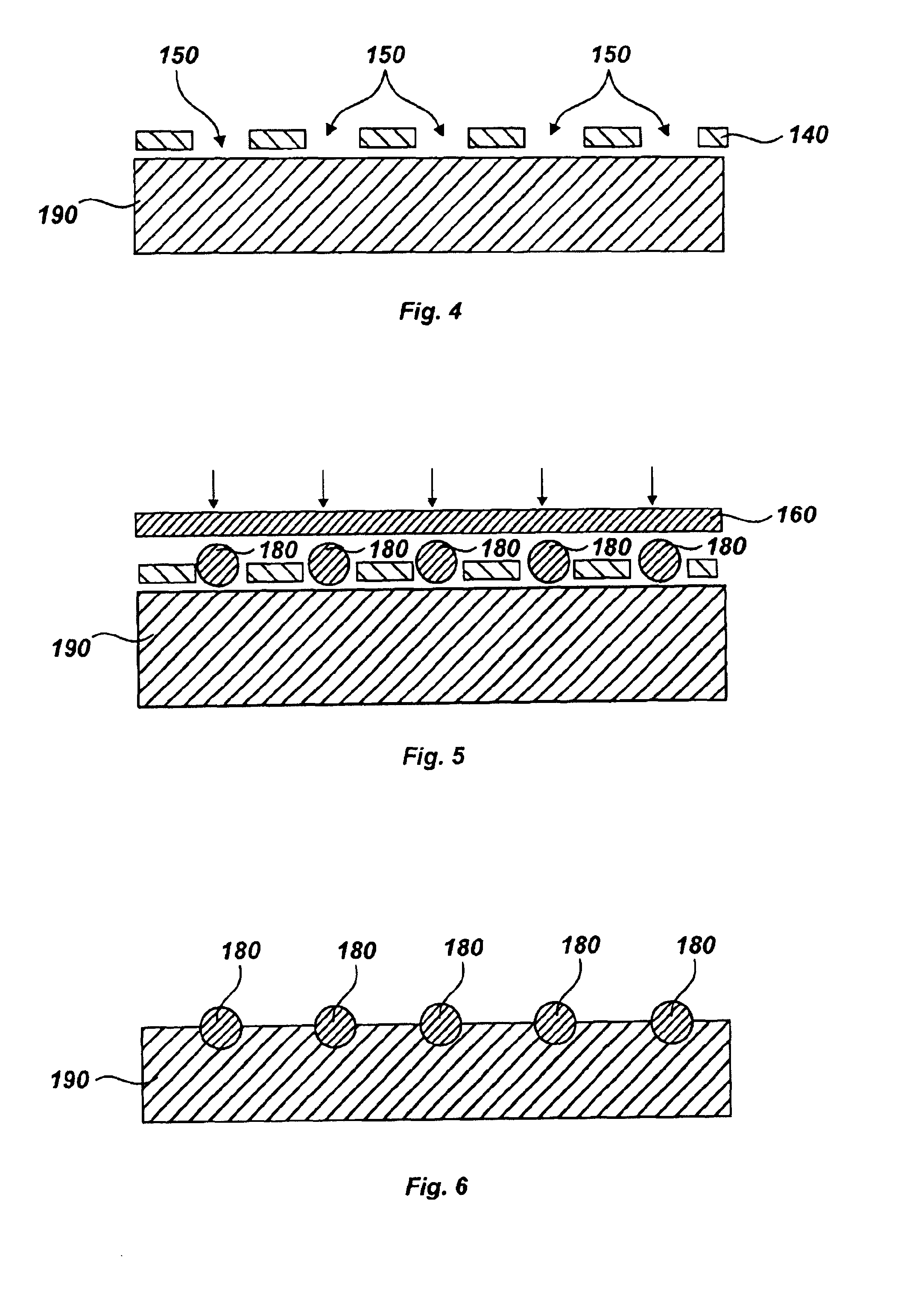
[0014]In an alternative embodiment, the abrasive particles may be affixed to a transfer sheet and then transferred to the brazing alloy. In one aspect of this embodiment, the transfer sheet can be made of metal or plastic, and may be flexible or rigid. Preferably, the transfer sheet is made of transparent plastic such that the transfer of superabrasive particles can be easily monitored. The affixing of superabrasive particles to the transfer plate or film can be facilitated by coating the transfer sheet with a thin layer of adhesive. The template is then used to distribute the abrasive particles onto the transfer sheet in the desired predetermined pattern. The transfer sheet having abrasive particles adhered thereto on one side is then pressed against the brazing alloy. The abrasive particles are transferred to the brazing alloy by either embedding therein, or by adhering to an adhesive that is coated on the surface thereof. The adhesive coated on the brazing alloy adheres the abrasive particles more strongly than the adhesive coated on the transfer sheet, and thus allows the particles to be transferred thereto. Notably, in each of the above-recited processes, the brazing alloy may be presented as either a sheet, or a punched out layer that
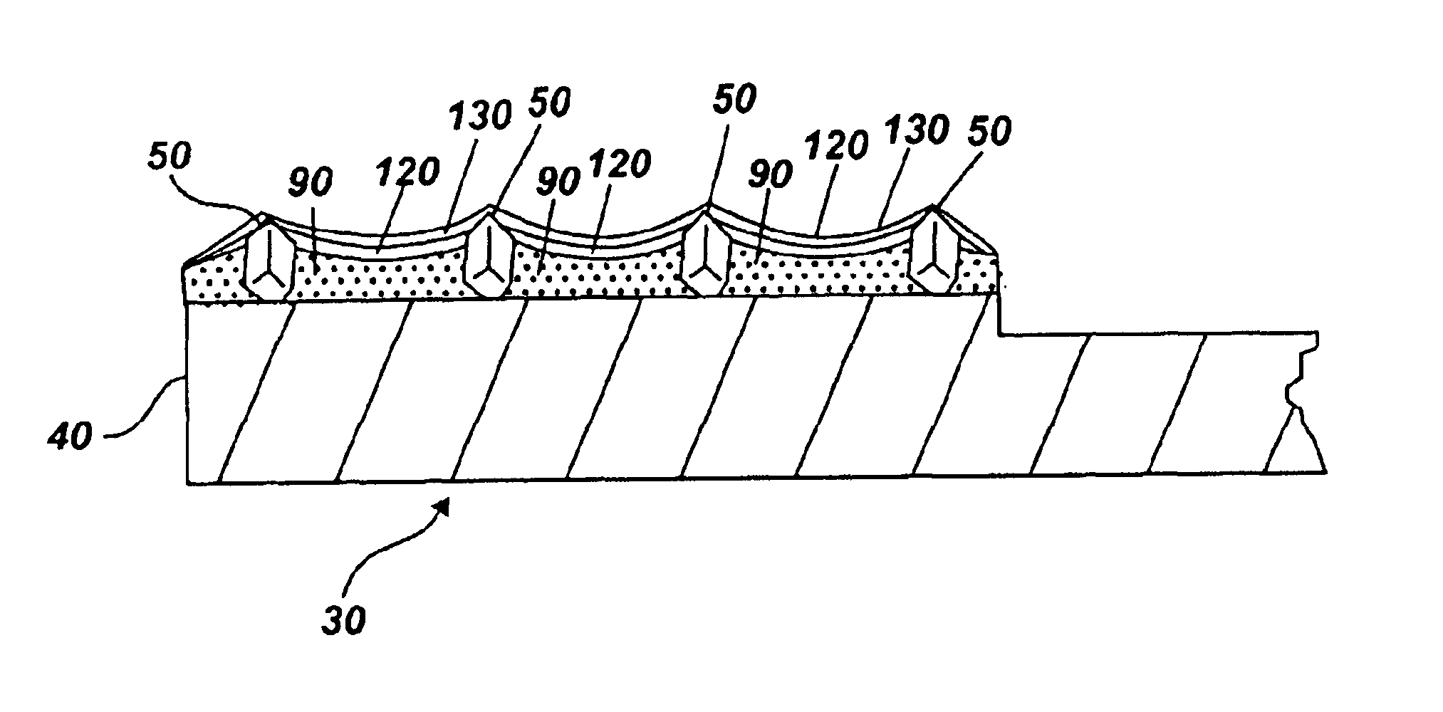
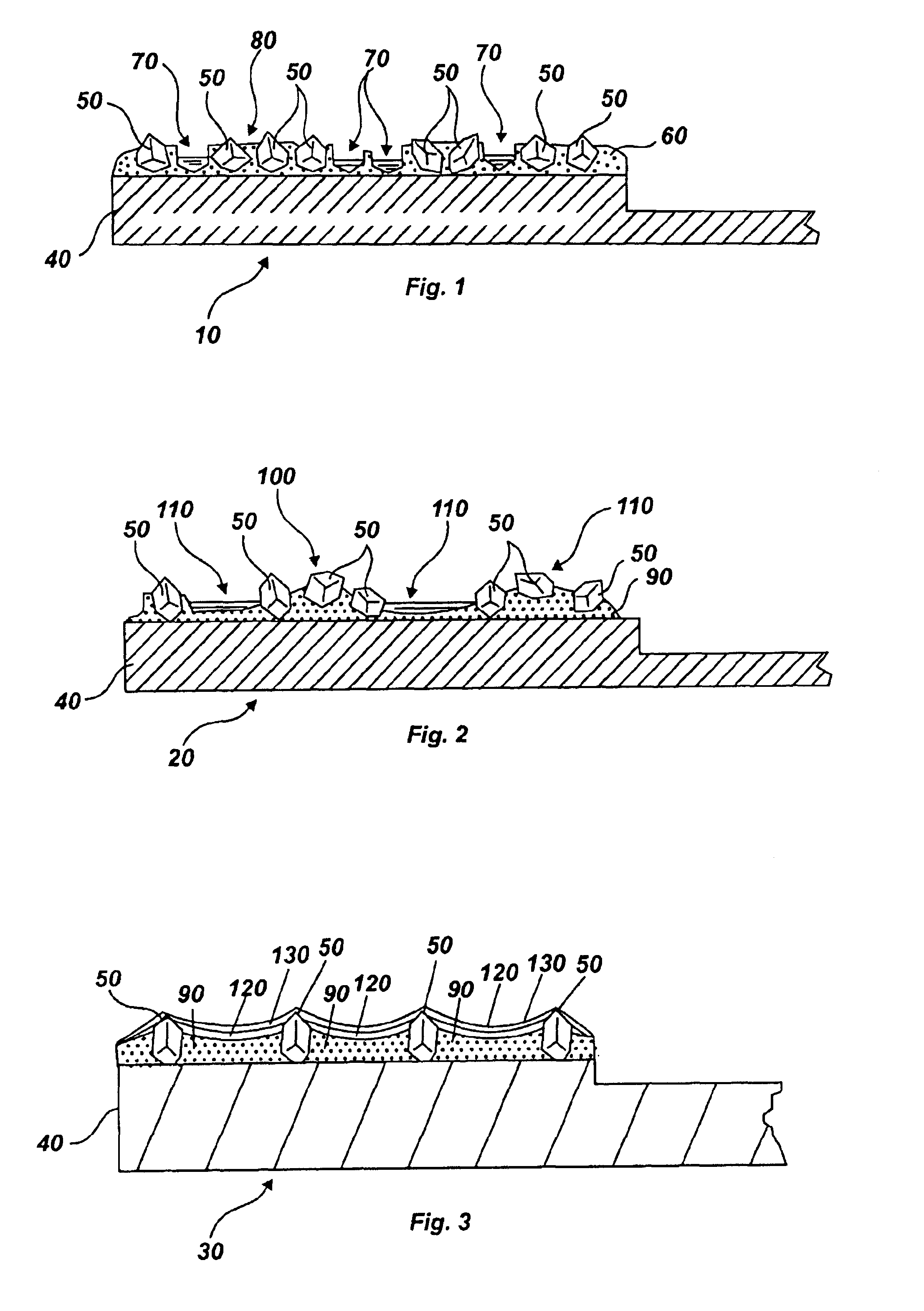
[0022]Use of the template also provides the ability to uniformly space the abrasive particles on the substrate. Uniform spacing of the abrasive particles upon the substrate also allows for a more even dressing of the pad across its surface. Additionally, by using a template with uniformly sized apertures, a uniform size of each abrasive particle is ensured. Finally, using a flat surface to press the abrasive particles into the substrate creates a uniform height of the abrasive particles protruding above the substrate surface. This uniform height of abrasive particles ensures cutting, or dressing of the CMP pad to a uniform depth. Alternatively, the use of a brazing alloy in a sheet or cut out with an even surface, in connection with uniformly sized abrasive particles that are adhered thereto, allows the creation of a uniform height between the abrasive particles.

Problems solved by technology

A problem with maintaining the top of the pad is caused by an accumulation of polishing debris coming from the work piece, abrasive slurry, and dressing disk.
This accumulation causes a “glazing” or hardening of the top of the pad, and mats the fibers down, thus making the pad less able to hold the abrasive particles of the slurry, and significantly decreasing the pad's overall polishing performance.
Further, with many pads, the pores used to hold the slurry, become clogged, and the overall asperity of the pad's polishing surface becomes depressed and matted.
Unfortunately, such abrasive disks made by conventional methods exhibit several problems.
First, abrasive particles may dislodge from the substrate of the disk and become caught in the CMP pad fibers.
This leads to scratching and ruin of the work piece being polished.
Second, the production methods of the past tend to produce disks having abrasive particles that are clustered in unevenly spaced groups on the surface of the substrate.
The resultant non-uniform spacing between particles causes some portions of the CMP pad to be overdressed which creates wear marks, while others are underdressed which creates glazing layers.
Third, the abrasive particles of these disks do not extend to a uniform height above the substrate surface of the disk.
This non-uniformity in height creates additional uneven dressing of the CMP pad, because many particles from the dresser may not touch the pad.
This depression causes the remaining abrasive particles on the pad dresser to skip over the pad fibers thereby causing the pad to be unevenly dressed.
Two factors tend to cause the abrasive particles to dislodge from the pad dresser disks of the prior art.
First, dislodging often occurs due to the inferior method by which the abrasive particles have been attached.
Hence, these particles become easily dislodged upon exposure to strong mechanical forces such as friction.
However, the acids of the chemical slurry quickly weaken the braze-particle bonds and dislodge the abrasive particles under the friction of pad dressing.
The resultant sequence of alternating polishing and then dressing wastes time, and is inefficient.
Warping of the pad dresser working surface during the brazing process also often causes abrasive particles to dislodge.
Exposure to this extreme heat can cause the working surface of the pad dresser to warp, thus compromising the smoothness and planarity of the pad dresser's working surface.
As a result, the braze portion of the working surface will be rough, having high and low spots.
Such spots are undesirable, as they may cause the braze to begin flaking off, and making micro-scratches on the polished surface of the work piece.
Further, such unevenness may cause issues with further processing of the dresser, and abrasive particle retention.

Method used


Image

  • Diamond grid CMP pad dresser
  • Diamond grid CMP pad dresser
  • Diamond grid CMP pad dresser

Examples


Embodiment Construction

[0033]Before the present CMP pad dresser and accompanying methods of use and manufacture are disclosed and described, it is to be understood that this invention is not limited to the particular process steps and materials disclosed herein, but is extended to equivalents thereof as would be recognized by those ordinarily skilled in the relevant arts. It should also be understood that terminology employed herein is used for the purpose of describing particular embodiments only and is not intended to be limiting.

[0034]It must be noted that, as used in this specification and the appended claims, the singular forms “a,” and, “the” include plural referents unless the context clearly dictates otherwise. Thus, for example, reference to an “abrasive particle” or a “grit” includes reference to one or more of such abrasive particles or grits.

Definitions

[0035]In describing and claiming the present invention, the following terminology will be used in accordance with the definitions set forth bel...


PUM

PropertyMeasurementUnit
sizeaaaaaaaaaa
sizeaaaaaaaaaa
thicknessaaaaaaaaaa

Abstract

The present invention discloses a CMP pad dresser which has a plurality of uniformly spaced abrasive particles protruding therefrom. The abrasive particles are super hard materials, and are typically diamond, polycrystalline diamond (PCD), cubic boron nitride (cBN), or polycrystalline cubic boron nitride(PcBN). The abrasive particles are brazed to a substrate which may be then coated with an additional anti-corrosive layer. The anti-corrosive layer is usually a diamond or diamond-like carbon which is coated over the surface of the disk to prevent erosion of the brazing alloy by the chemical slurry used in conjunction with the CMP pad. This immunity to chemical attack allows the CMP pad dresser to dress the pad while it is polishing a workpiece. In addition to even spacing on the substrate, the abrasive particles extend for a uniform distance away from the substrate, allowing for even grooming or dressing of a CMP pad both in vertical and horizontal directions. A method of producing such a CMP pad dresser is also disclosed.

Description

PRIORITY DATA[0001]This patent application is a continuation-in-part of U.S. patent application Ser. No. 09 / 558,582 filed Apr. 26, 2000 now U.S. Pat. No. 6,368,198, which is a continuation-in-part of U.S. patent application Ser. No. 09 / 447,620 filed Nov. 22, 1999, now abandoned.FIELD OF THE INVENTION[0002]The present invention relates generally to a device and methods for dressing or conditioning a chemical mechanical polishing (CMP) pad. Accordingly, the present invention involves the chemical and material science fields.BACKGROUND OF THE INVENTION[0003]Many industries are now using a chemical mechanical process (CMP) for polishing certain work pieces. Particularly, the computer manufacturing industry has begun to rely heavily on CMP processes for polishing wafers of ceramics, silicon, glass, quartz, and metals thereof. Such polishing processes generally entail applying the wafer against a rotating pad made from a durable organic substance such as polyurethane. To the pad, is added...

Claims


Application Information

Patent Timeline
Patent Type & Authority Patents(United States)
IPC IPC(8): B24D7/00B24D7/02B24D3/06B24D3/04B24B37/04B24B53/12B24B53/017
CPCB24B53/017B24D7/02B24D3/06B24B53/12B24D2203/00
Inventor SUNG, CHIEN-MINLIN, FRANK
Owner KINIK
Why Eureka
Try Eureka