Deposition apparatus for organic light-emitting devices

a technology of light-emitting devices and deposition apparatuses, which is applied in the direction of electrolysis components, vacuum evaporation coatings, coatings, etc., can solve the problems of large damage to organic light-emitting devices, the organic emitting materials of organic light-emitting devices are very sensitive to water and oxygen, and the damage of organic light-emitting devices is the major cause of damage, etc., to reduce the possibility of substrate pollution, shorten the transferring substrate time and reduce the possibility of pollution

Inactive Publication Date: 2005-04-26
RITDISPLAY
View PDF9 Cites 8 Cited by
  • Summary
  • Abstract
  • Description
  • Claims
  • Application Information

AI Technical Summary

Benefits of technology

[0014]The present invention provides a deposition apparatus for an organic light-emitting device, which transfers substrates synchronously so as to greatly shorten the transferring time of substrates.
[0015]It is an objective of the invention to provide a deposition apparatus to shorten time lost during substrate transferring and loading / unloading, reduce possibility of substrate pollution, and increase transferring stability.
[0016]It is another objective of the invention to provide a deposition apparatus to reduce evaporation time and cycle time of device manufacturing, decrease cost of device manufacturing, and greatly reduce the cost of machines.
[0017]To achieve the above objectives, a deposition apparatus of this invention includes a substrate conveying system having a circular turntable shape, and at least a chamber provided around the substrate conveying system in a specific order. While the substrate conveying system rotates in a circular direction, at least a substrate is synchronously transferred into the chambers so as to shorten time lost during substrate transferring and loading / unloading, reduce possibility of substrate pollution, and increase transferring stability. The substrate, a shadow mask and a shadow mask alignment system are positioned on a substrate carrier. After that, a deposition process is implemented to form at least a layer on the substrates. In the current invention, the chambers include a loading / unloading chamber and a variety of deposition chambers. The deposition chambers of this invention are utilized for depositing an organic emitting layer, a cathode layer, an anode layer, and / or a passivation layer.

Problems solved by technology

However, organic light-emitting devices are not suitable for large-scale manufacturing.
It is a big issue to develop an organic light-emitting device with long-term use.
In particular, organic emitting materials of organic light-emitting devices are very sensitive to water and oxygen.
In the present research, water and oxygen are the major cause of damage of the organic light-emitting devices.
They are also the major limitation why the current organic light-emitting devices cannot be commercialized.
Furthermore, the conventional deposition apparatus or coating apparatus utilizes a robot arm (3-dimensional) to transfer the substrates, so time lost in transferring substrates is increased.
Therefore, the throughput of deposition apparatuses is greatly reduced, and the deposition process becomes the chock point of the manufacturing and decreases the benefit of other process machines such as photolithography apparatuses and package apparatuses.
In this case, because the loading / unloading chamber 11 has to store a lot of substrates (no more than 25 pieces of substrates in general) and has a big size, the cluster deposition apparatus may waste much time on exhausting gases.
In addition, there are many idle chambers, so that the throughput of the cluster deposition apparatus cannot be raised efficiently.
Moreover, in those idle chambers, some expensive organic materials are wasted.
Because the chambers are too large, it wastes much time on exhausting gases.

Method used


Image

  • Deposition apparatus for organic light-emitting devices
  • Deposition apparatus for organic light-emitting devices
  • Deposition apparatus for organic light-emitting devices

Examples


Embodiment Construction

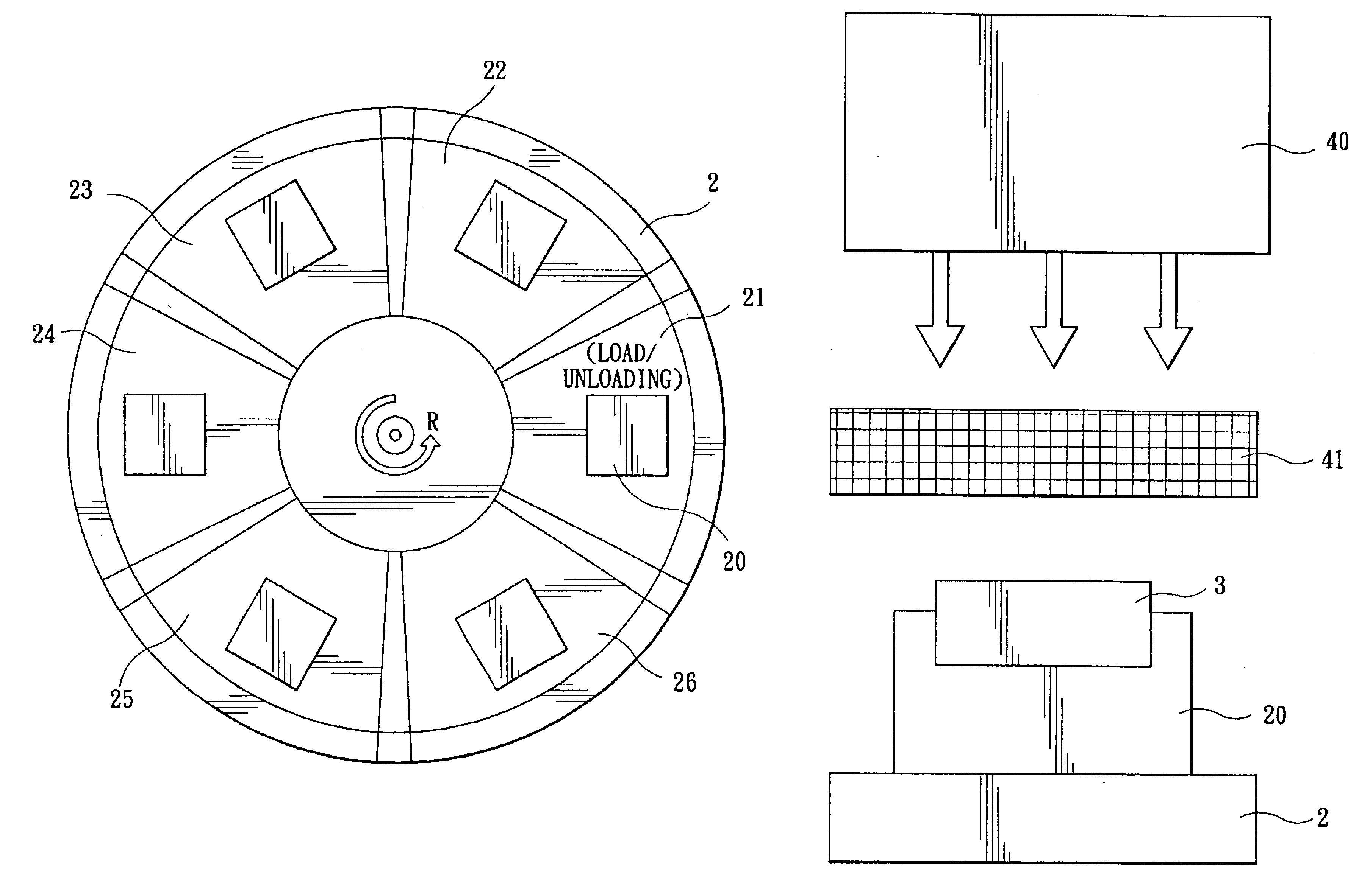
[0024]In general, an organic light-emitting device mainly includes a substrate, an anode layer, an organic emitting layer, a cathode layer, and a passivation layer. The organic emitting layer includes a hole injecting layer, a hole transporting layer, a luminescent layer, an electron transporting layer, and an electron injecting layer. This invention mainly provides a deposition apparatus of organic light-emitting devices, which utilizes a substrate conveying system with a circular turntable shape to transfer a substrate into each chamber for deposition in turn. Therefore, each of the mentioned layers is formed on a plurality of substrates. An embodiment of the present invention will hereinafter be explained in detail.

[0025]Referring to FIGS. 2 and 3, a deposition apparatus for organic light-emitting devices includes a substrate conveying system 2 and chambers 21, 22, 23, 24, 25, and 26. In the current embodiment, the substrate conveying system 2 is a circular turntable shape, and t...


PUM

PropertyMeasurementUnit
temperatureaaaaaaaaaa
thicknessaaaaaaaaaa
luminescentaaaaaaaaaa

Abstract

A deposition apparatus for organic light emitting devices. The deposition apparatus includes a substrate conveying system and at least a chamber. In this case, the substrate conveying system is a circular turntable shape. The chambers are provided around the substrate conveying system in a specific order. While the substrate conveying system rotates in a circular direction, at least a substrate is transferred into the chambers for deposition. The substrate carrier, a shadow mask and a shadow mask alignment system, are positioned on the substrate carrier. After the deposition, at least a layer is deposited on each of the substrates, so as to manufacture at least an organic light-emitting device.

Description

BACKGROUND OF THE INVENTION[0001]1. Field of Invention[0002]The invention relates to a deposition apparatus for organic light-emitting devices and, in particular, to a deposition apparatus having a substrate conveying system between chambers.[0003]2. Related Art[0004]An organic light-emitting device which is excited by electric current, has advantages of planar, high contrast, fast displaying speed, simplify structure, lighter, high outdoor visibility, low electrical consuming, and high luminance. Therefore, the organic light-emitting device is one of the most potential displays recently. However, organic light-emitting devices are not suitable for large-scale manufacturing. It is a big issue to develop an organic light-emitting device with long-term use.[0005]Generally, manufacturing processes of an organic light-emitting device include three stages:[0006](1) After a cleaning step, a substrate is transferred into an anode deposition machine for depositing an anode layer, and a phot...

Claims


Application Information

Patent Timeline
Patent Type & Authority Patents(United States)
IPC IPC(8): C23C14/56
CPCC23C14/568
Inventor CHANG, YIWANG, JIH-YIWEI, MAO-KUOLU, TIEN-RONG
Owner RITDISPLAY
Why Eureka
Try Eureka