
Composite magnetic sheet and method of producing the same

a magnetic sheet and composite technology, applied in the field of composite magnetic sheets, can solve the problems of increasing line coupling, noise may influence the external apparatus, inhibit the normal operation of the apparatus,

Inactive Publication Date: 2005-05-03
TOKIN CORP
View PDF10 Cites 14 Cited by
  • Summary
  • Abstract
  • Description
  • Claims
  • Application Information

AI Technical Summary

Benefits of technology

[0018]It is therefore an object of this invention to provide a method of producing a composite magnetic sheet which is improved in electromagnetic interference suppressing effect in a FM band (several tens to a hundred MHz) without decreasing a high permeability of flat soft magnetic powder free from stress strain and at a low cost.
[0019]It is another object of this invention to provide a composite magnetic sheet which is improved in electromagnetic interference suppressing effect in a FM band without decreasing a high permeability of flat soft magnetic powder free from stress strain and at a low cost.

Problems solved by technology

This results in an increase in line coupling due to capacitive coupling and electromagnetic coupling and in occurrence of interference due to radiation noise to often inhibit normal operation of the apparatus.
Sometimes, such noise may have an influence upon external apparatuses.
Therefore, an emergent demand can not be met.
The above-mentioned composite magnetic sheet used in the submicrometer wave band becomes insufficient in permeability as the frequency is lowered.
However, ferrite can not be mounted because of the possibility of fracture and the problem of the location.
Even if there is such adaptable component, much cost and manhour are required in design modification of a substrate and the like.
However, a sufficient value of μ′ can not be obtained by film formation alone and, therefore, pressing by the use of the press is performed to achieve high permeability.
Therefore, it is difficult to reduce the cost in case where the production amount is increased.
In this event, mechanical stress strain is produced again in the flat soft magnetic powder free from stress strain so that desired magnetic characteristics can not be obtained.
From the abovementioned reasons, a number of problems exist when the composite magnetic body adapted to the band between several tens and a hundred MHz is produced with the above-mentioned method.

Method used


Image

  • Composite magnetic sheet and method of producing the same
  • Composite magnetic sheet and method of producing the same
  • Composite magnetic sheet and method of producing the same

Examples


Embodiment Construction

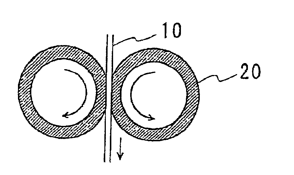
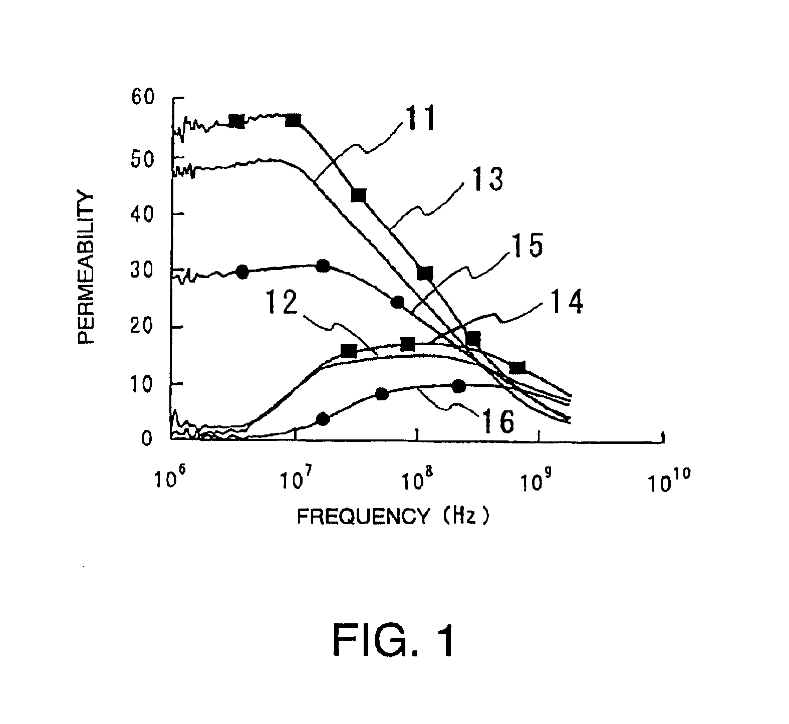
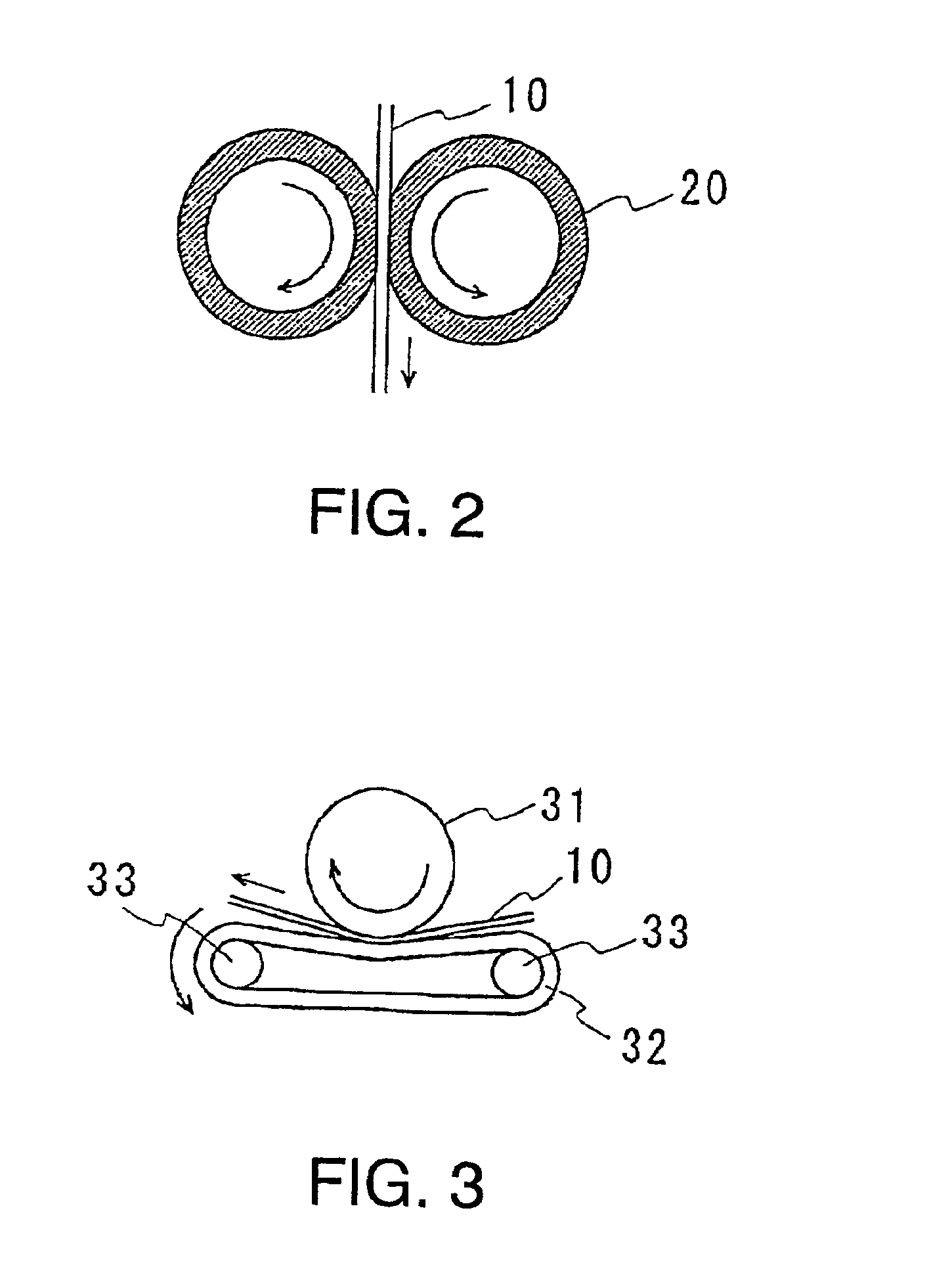
[0047]Now, an embodiment of this invention will be described in detail with reference to the drawing.

[0048]As flat soft magnetic powder, preparation was made of Sendust (Fe—Si—Al) alloy powder having an average grain size of 35 μm and an aspect ratio of 5 or more. In order to remove stress strain, the flat soft magnetic powder was subjected to annealing in a nitrogen atmosphere at 650% for 2 hours.

[0049]Measurement was made of 85 wt % of the flat soft magnetic powder after the annealing, 14 wt % of chlorinated polyethylene as a binder, 1 wt % of a coupling agent, and 20 wt % of toluene as a solvent. For titanate-based and silane-based coupling agents, individual samples were separately prepared.

[0050]Next, the flat soft magnetic powder was fed into a planetary mixer. While agitating, the coupling agent was supplied. Agitation was performed for five minutes. Thereafter, chlorinated polyethylene preliminarily dissolved into a predetermined amount of the solvent was supplied and agitat...


PUM

PropertyMeasurementUnit
frequencyaaaaaaaaaa
grain sizeaaaaaaaaaa
thicknessaaaaaaaaaa

Abstract

In a method of producing a composite magnetic body, flat soft magnetic powder subjected to annealing to be free from stress strain is prepared and mixed with a binder and a solvent for dissolving the binder to form a slurry-like mixture. The mixture is formed into a film. Then, the solvent is removed. Thus, a sheet of the composite magnetic body is produced.

Description

BACKGROUND OF THE INVENTION[0001]This invention relates to a composite magnetic body and a method of manufacturing the composite magnetic body. The composite magnetic body is usable as an electromagnetic interference suppressor for use in an electronic apparatus to prevent leakage of an extraneous radio wave to the outside, interference between internal circuits, and influence of an external radio wave such as malfunction.[0002]In recent years, it is a matter of great concern to cope with a problem as to an electromagnetic environment of an electronic apparatus. In the background, there are various requirements for an electronic equipment such as a digital electronic apparatus to increase a signal processing speed of a circuit, to use a higher frequency, to provide improved functions, to reduce the size and the thickness of a product design, and so on. To meet these requirements, the circuit is increased in density so that active elements and passive elements, such as semiconductor ...

Claims


Application Information

Patent Timeline
Patent Type & Authority Patents(United States)
IPC IPC(8): H01F1/00H01F41/14H01F41/16H05K9/00
CPCH01F1/0027H05K9/0083H01F41/16Y10S264/58
Inventor ONO, NORIHIKO
Owner TOKIN CORP
Learn More