
Catalyst system for enhanced flow syngas production

a catalyst system and enhanced flow technology, applied in the field of apparatus and methods for the production of synthesis gas, can solve the problems of unattractive economic use of this remote natural gas in most instances, undesirable long catalyst beds, waste of expensive catalysts and reactor space, etc., to increase the conversion and selectivity, increase the overall methane conversion, and increase the length of the catalyst bed

Inactive Publication Date: 2005-05-03
PHILLIPS 66 CO
View PDF7 Cites 41 Cited by
  • Summary
  • Abstract
  • Description
  • Claims
  • Application Information

AI Technical Summary

Benefits of technology

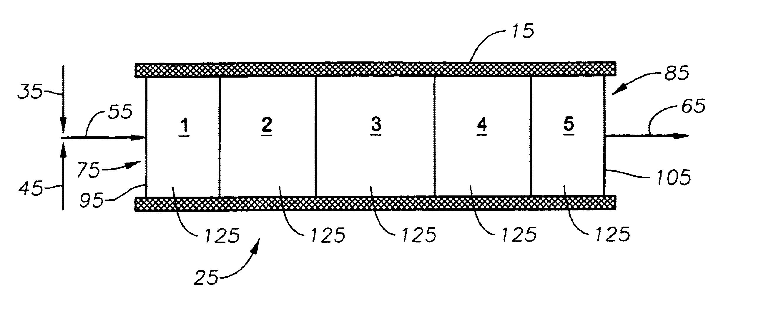
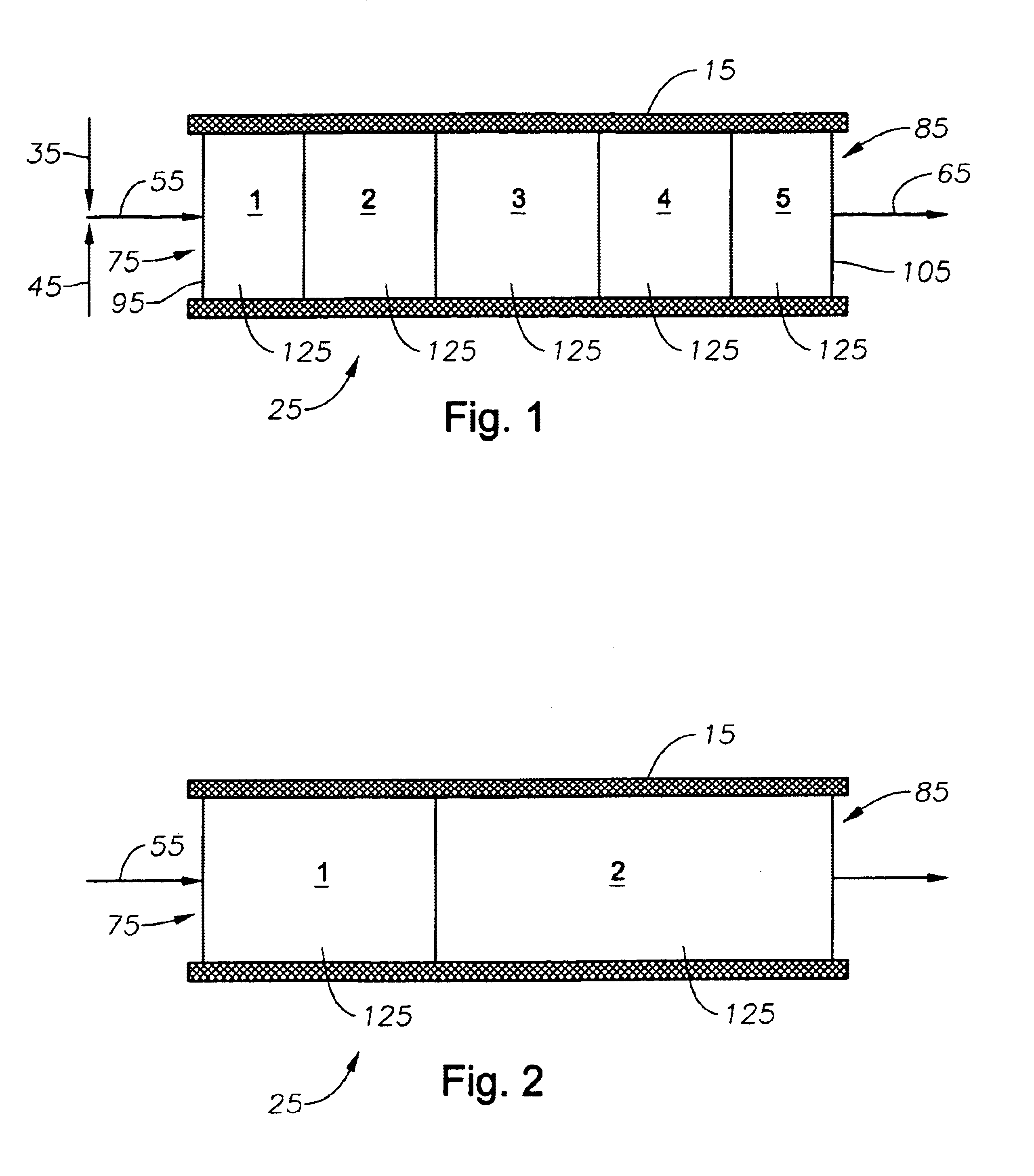
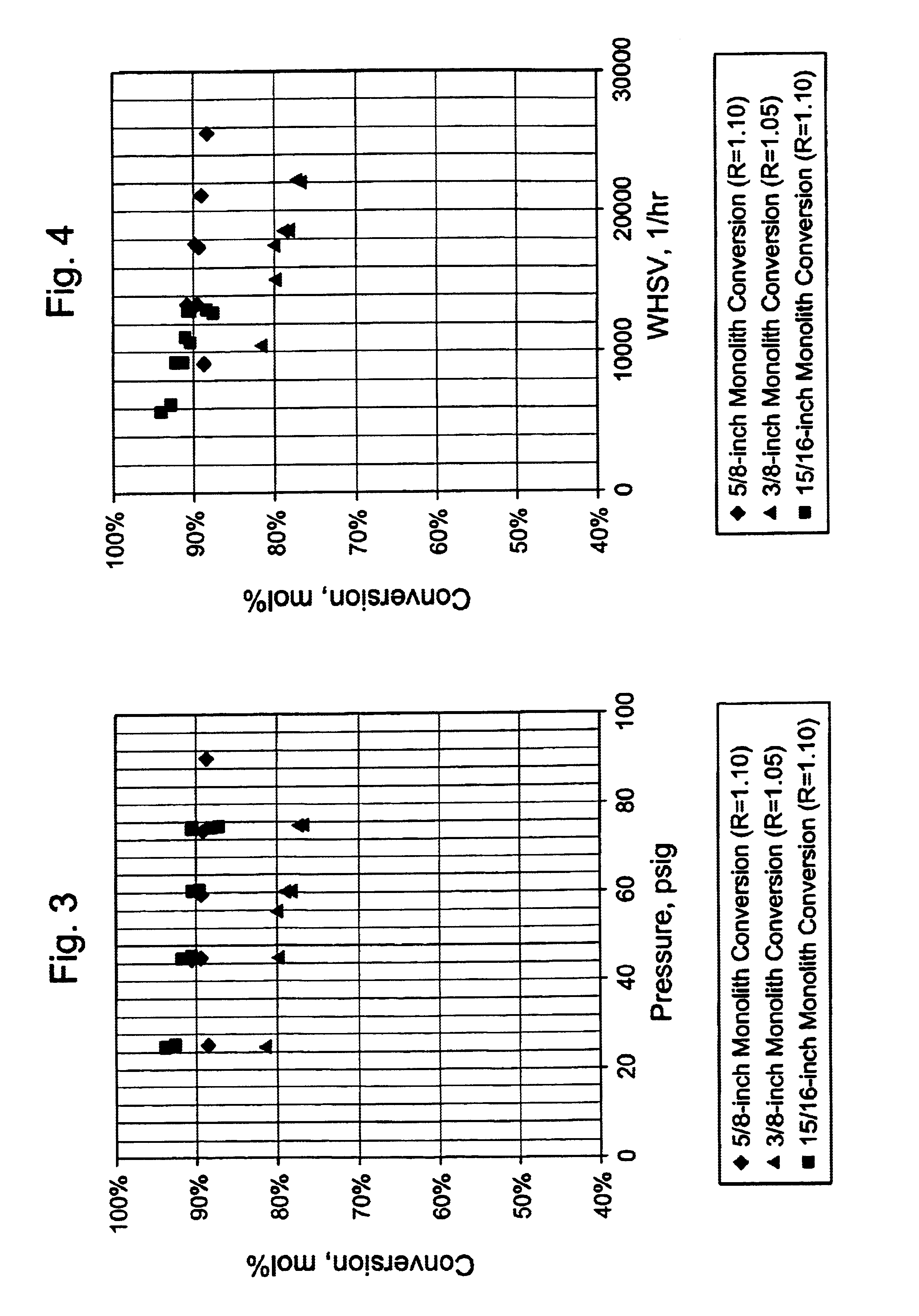
[0014]Accordingly, there is provided herein a catalyst system which increases the conversion and selectivity of the catalytic partial oxidation of hydrocarbons to the desired products, such as syngas, and increases the overall methane conversion without creating an undesirably large pressure drop across the catalyst bed. We have discovered that increasing the length of the catalyst bed gives higher hydrocarbon conversion, higher syngas selectivities, more stable operation, and less coking.
[0015]The catalyst system is capable of operating at elevated pressure to provide high space velocities, which is particularly desirable in short contact time catalytic partial oxidation reactors like those used for the production of synthesis gas from gaseous light hydrocarbons.

Problems solved by technology

However, most natural gas is situated in areas that are geographically remote from population and industrial centers.
The costs of compression, transportation, and storage make the use of this remote natural gas economically unattractive in most instances.
Thus, because it is thought that only a small portion of the catalyst bed is needed to catalyze the reaction, it should logically follow that catalyst beds longer than 1 mm would waste expensive catalyst and reactor space.
Additionally, in some instances, longer catalyst beds are undesirable because it is difficult or impossible to maintain high gas hourly space velocities and short contact times.

Method used


Image

  • Catalyst system for enhanced flow syngas production
  • Catalyst system for enhanced flow syngas production
  • Catalyst system for enhanced flow syngas production

Examples


example

Procedure for Preparation of Rh / Sm / PSZ Catalysts

[0037]An aqueous solution of samarium nitrate [Sm(NO3)3] was added dropwise to saturate a PSZ monolith. Suitable PSZ monoliths about 10 or 15 mm long and 12 mm diameter are commercially available from well known sources. The monolith was situated on a Teflon® plate residing on a warm (75° C.) hotplate. The entire samarium salt solution was gradually added to the monolith, allowing the water to evaporate between saturations. The dried monolith was then calcined in air (static or flowing) according to the following program: heat from room temperature (RT) to about 125° C. at a rate of about 5° C. / min, dwell at that temperature for about 60 min (extra drying step); heat from about 125° C. to about 400-900° C., preferably about 600° C., at a rate of about 1-10° C. / min, preferably about 5° C. / min, dwell at that temperature for about 120-360 min, or more, preferably about 240 min.

[0038]An aqueous solution of rhodium chloride [RhCl3.xH2O] was...


PUM

PropertyMeasurementUnit
Fractionaaaaaaaaaa
Timeaaaaaaaaaa
Timeaaaaaaaaaa

Abstract

A method and apparatus for converting a hydrocarbon and oxygen containing gas feed stream to a product stream, such as syngas, including catalytically partially oxidizing the hydrocarbon feed stream over a catalyst bed. The catalyst bed has a downstream section which is less resistant to flow than the upstream section.

Description

CROSS REFERENCE TO RELATED APPLICATIONS[0001]The present application claims priority to U.S. Provisional Application No. 60 / 327,479, filed Oct. 5, 2001 incorporated herein by reference.STATEMENT REGARDING FEDERALLY SPONSORED RESEARCH[0002]Not applicable.FIELD OF THE INVENTION[0003]The present invention generally relates to apparatus and methods for the production of synthesis gas, a mixture of primarily CO and H2. Particularly, the present invention relates to optimizing the production of synthesis gas by controlling the properties of the catalyst bed. More particularly, the present invention relates to optimizing the production of synthesis gas by controlling the flow resistance and length of the catalyst bed and the pressure drop across the bed.BACKGROUND OF THE INVENTION[0004]Large quantities of natural gas, comprising mostly methane, are available in many areas of the world, and natural gas is predicted to outlast oil reserves by a significant margin. However, most natural gas i...

Claims


Application Information

Patent Timeline
IPC IPC(8): B01J8/04B01J19/24B01J23/63B01J21/06B01J21/00B01J23/54B01J12/00B01J35/00B01J37/00B01J37/02B01J35/04C01B3/00C01B3/38C01B3/40
CPCB01J8/0415B01J12/007B01J19/2485B01J21/06B01J21/066B01J23/63B01J35/0006B01J35/04B01J37/0205C01B3/386C01B3/40B01J8/0438C01B2203/82B01J2208/00548B01J2208/025B01J2219/00164B01J2219/00166B01J2219/182C01B2203/0261C01B2203/1011C01B2203/1017C01B2203/1023C01B2203/1047C01B2203/1052C01B2203/1064C01B2203/1082C01B2203/1235C01B2203/1241C01B2203/142C01B2203/143Y02P20/52B01J35/19B01J35/56
Inventor XU, BANG CHENRAMANI, SRIRAMRICKETSON, KEVIN L.STRAGUZZI, GLORIA I.SWINNEY, LARRY D.ALLISON, JOE D.
Owner PHILLIPS 66 CO
Learn More