LNG production in cryogenic natural gas processing plants

a technology of cryogenic natural gas and processing plants, which is applied in the direction of refrigeration and liquifaction, lighting and heating apparatus, solidification, etc., can solve the problems of reducing the purity (i.e., methane concentration) of the lng product, affecting the value of liquid products for the plant operator, and affecting the quality of the liquid produ

Inactive Publication Date: 2005-05-10
ORTLOFF ENGINEERS
View PDF66 Cites 70 Cited by
  • Summary
  • Abstract
  • Description
  • Claims
  • Application Information

AI Technical Summary

Benefits of technology

[0007]While any of these methods could be employed to produce vehicular grade LNG, the capital and operating costs associated with these methods have generally made the installation of such facilities uneconomical. For instance, the purification steps required to remove water, carbon dioxide, sulfur compounds, etc. from the natural gas prior to liquefaction represent considerable capital and operating costs in such facilities, as do the drivers for the refrigeration cycles employed. This has led the inventors to investigate the feasibility of integrating LNG production into cryogenic gas processing plants used to recover NGL from natural gas. Such an integrated LNG production method would eliminate the need for separate gas purification facilities and gas compression drivers. Further, the potential for integrating the cooling / condensation for the LNG liquefaction with the process cooling required for NGL recovery could lead to significant efficiency improvements in the LNG liquefaction method.
[0008]In accordance with the present invention, it has been found that LNG with a methane purity in excess of 99 percent can be co-produced from a cryogenic NGL recovery plant without reducing the NGL recovery level using less energy than prior art processes. The present invention, although applicable at lower pressures and warmer temperatures, is particularly advantageous when processing feed gases in the range of 400 to 1500 psia [2,758 to 10,342 kPa(a)] or higher under conditions requiring NGL recovery column overhead temperatures of −50° F. [−46° C.] or colder.

Problems solved by technology

Although there are many different processes that can be used for carbon dioxide removal, many of them will cause the treated gas stream to become partially or completely saturated with water.
Since water in the feed stream would also lead to freezing problems in the LNG production section, it is very likely that the carbon dioxide removal section 50 must also include dehydration of the gas stream after treating.
Consequently, all of the heavier hydrocarbons present in the feed gas become part of the LNG product, reducing the purity (i.e., methane concentration) of the LNG product.
Unfortunately, this means that the C2 components, C3 components, and heavier hydrocarbon components removed from the LNG feed stream would not be recovered in the NGL product from the NGL recovery plant, and their value as liquid products would be lost to the plant operator.
Further, for feed streams such as the one considered in this example, condensation of liquid from the feed stream may not be possible due to the process operating conditions (i.e., operating at pressures above the cricondenbar of the stream), meaning that removal of heavier hydrocarbons could not be accomplished in such instances.
However, this comes at the expense of increasing the utility consumption for the FIG. 3 process.

Method used


Image

  • LNG production in cryogenic natural gas processing plants
  • LNG production in cryogenic natural gas processing plants
  • LNG production in cryogenic natural gas processing plants

Examples


Embodiment Construction

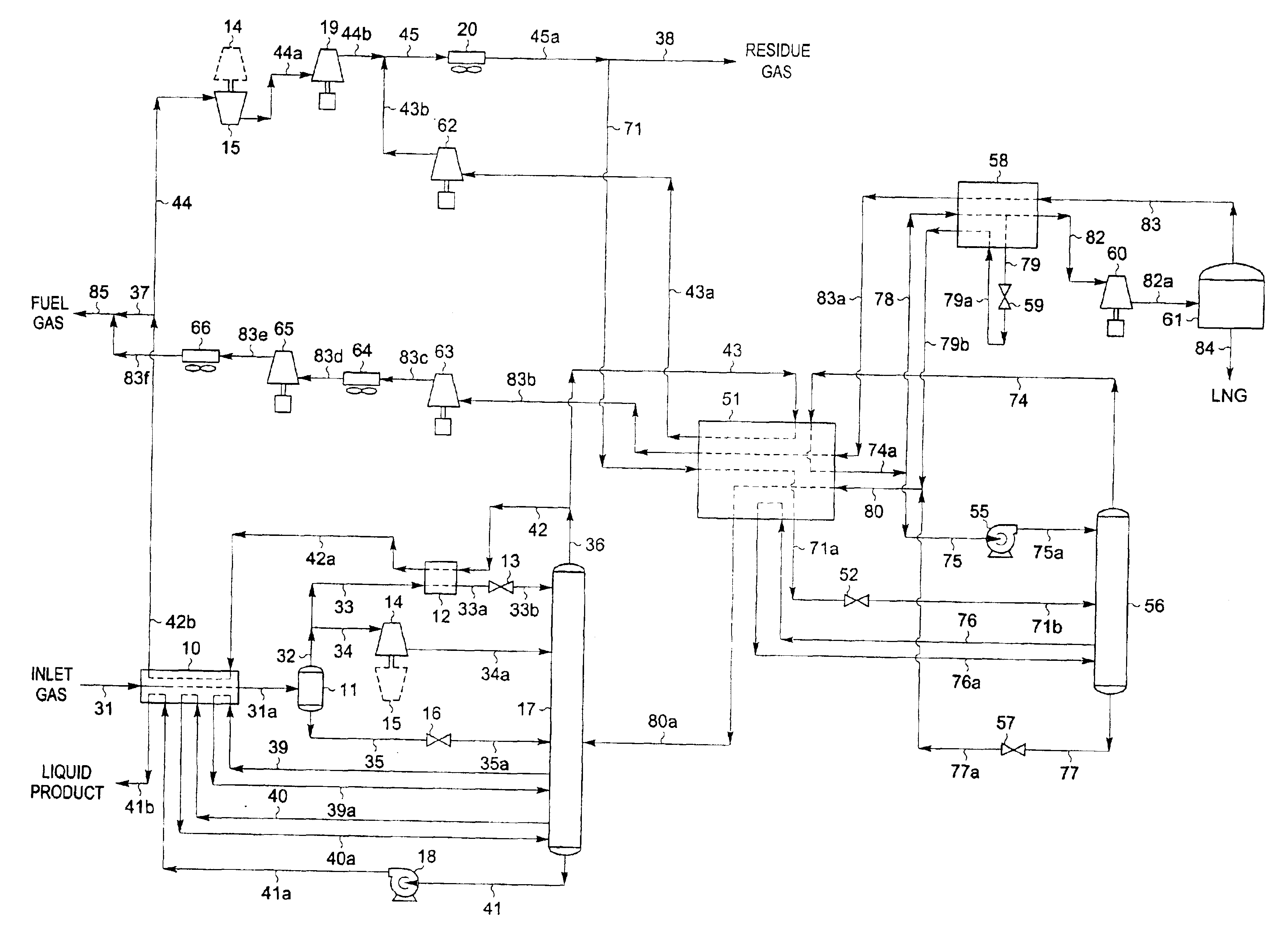
[0072]FIG. 5 illustrates a flow diagram of a process in accordance with the present invention. The inlet gas composition and conditions considered in the process presented in FIG. 5 are the same as those in FIGS. 1 through 4. Accordingly, the FIG. 5 process can be compared with that of the processes in FIGS. 2, 3, and 4 to illustrate the advantages of the present invention.

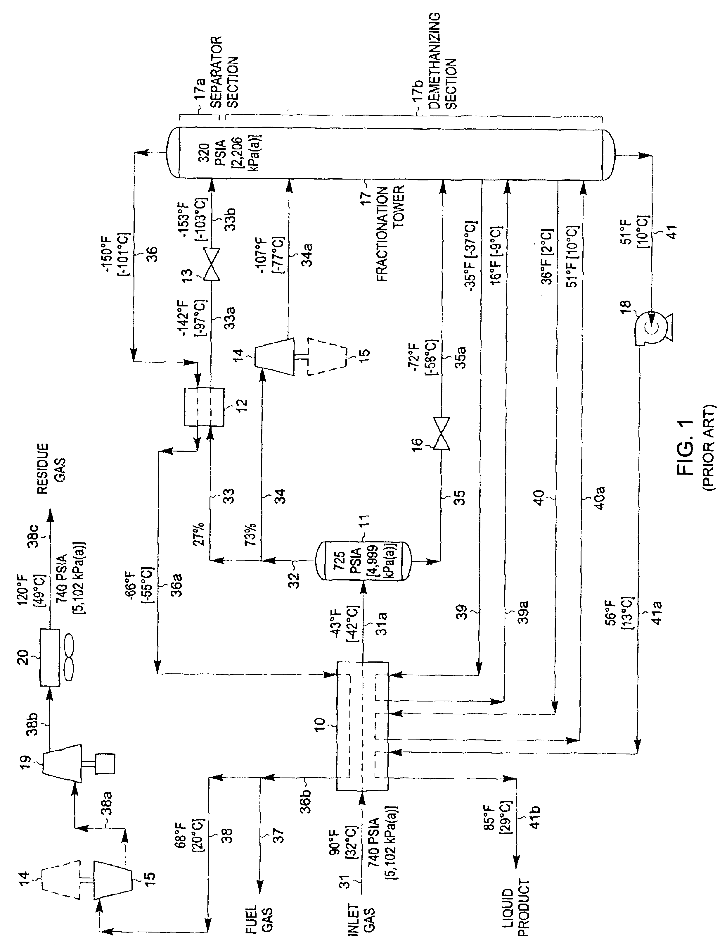
[0073]In the simulation of the FIG. 5 process, the inlet gas cooling, separation, and expansion scheme for the NGL recovery plant is essentially the same as that used in FIG. 1. The main differences are in the disposition of the cold demethanizer overhead vapor (stream 36) and the compressed and cooled third residue gas (stream 45a) produced by the NGL recovery plant. Inlet gas enters the plant at 90° F. [32° C.] and 740 psia [5,102 kPa(a)] as stream 31 and is cooled in heat exchanger 10 by heat exchange with cool demethanizer overhead vapor (stream 42a) at −66° F. [−55° C.], bottom liquid product at 53° F. [12° C...


PUM


Abstract

A process for liquefying natural gas in conjunction with processing natural gas to recover natural gas liquids (NGL) is disclosed. In the process, the natural gas stream to be liquefied is taken from one of the streams in the NGL recovery plant and cooled under pressure to condense it. A distillation stream is withdrawn from the NGL recovery plant to provide some of the cooling required to condense the natural gas stream. A portion of the condensed stream is expanded to an intermediate pressure and then used to provide some of the cooling required to condense the natural gas stream, and thereafter routed to the NGL recovery plant so that any heavier hydrocarbons it contains can be recovered in the NGL product. The remaining portion of the condensed stream is expanded to low pressure to form the liquefied natural gas stream.

Description

BACKGROUND OF THE INVENTION[0001]This invention relates to a process for processing natural gas to produce liquefied natural gas (LNG) that has a high methane purity. In particular, this invention is well suited to co-production of LNG by integration into natural gas processing plants that recover natural gas liquids (NGL) and / or liquefied petroleum gas (LPG) using a cryogenic process.[0002]Natural gas is typically recovered from wells drilled into underground reservoirs. It usually has a major proportion of methane, i.e., methane comprises at least 50 mole percent of the gas. Depending on the particular underground reservoir, the natural gas also contains relatively lesser amounts of heavier hydrocarbons such as ethane, propane, butanes, pentanes and the like, as well as water, hydrogen, nitrogen, carbon dioxide, and other gases.[0003]Most natural gas is handled in gaseous form. The most common means for transporting natural gas from the wellhead to gas processing plants and thence...

Claims


Application Information

Patent Timeline
Patent Type & Authority Patents(United States)
IPC IPC(8): F25J1/00F25J3/02
CPCF25J1/0201F25J3/0209F25J3/0233F25J3/0238F25J3/0242F25J1/0022F25J1/0035F25J1/004F25J1/0042F25J1/0045F25J1/0229F25J2260/20F25J2200/02F25J2200/04F25J2200/70F25J2200/72F25J2205/04F25J2210/06F25J2220/66F25J2230/60F25J2240/02F25J2240/30F25J2245/02F25J2245/90F25J2270/02F25J2270/90F25J2215/04
Inventor WILKINSON, JOHN D.HUDSON, HANK M.CUELLAR, KYLE T.
Owner ORTLOFF ENGINEERS
Why Eureka
Try Eureka