Thermal type flow rate detector

a flow rate detector and flow rate technology, applied in the direction of measuring devices, electrical control, instruments, etc., can solve the problems of difficult miniaturization of circuits, unnecessary temperature adjustment of heat generating elements, and problems such as detection accuracy becomes a problem, and achieve excellent sn ratio

Active Publication Date: 2005-05-10
MITSUBISHI ELECTRIC CORP
View PDF5 Cites 15 Cited by
  • Summary
  • Abstract
  • Description
  • Claims
  • Application Information

AI Technical Summary

Benefits of technology

[0022]As a result, there can be obtained such an effect that a flow direction can also be identified, and a flow rate signal of an analog voltage excellent in SN ratio can be obtained.

Problems solved by technology

While the heat generating element and the temperature detecting elements are made so as to be of a diaphragm structure of reducing the heat capacity by using the fine patterning of silicon, since the mechanical strength is ensured, the necessary responsibility cannot be obtained and hence the detection accuracy becomes a problem depending on the engine and its running state.
Moreover, since there is required a temperature difference detecting circuit for detecting the temperature difference between the fixed temperature detecting circuit and the temperature detecting elements on the upstream and downstream sides, the circuit is difficult to be miniaturized.
Thus, that detector has the merit that the temperature adjustment for the heat generating element becomes unnecessary.
In addition, the flow rate signal is mixed with the noise due to the switching operation, and in particular, when the flow rate sensitivity is low, the SN ratio becomes worse in some cases.
Then, if an analog voltage having small ripple is intended to be obtained, the cut-off frequency of the low-pass filter needs to be set to a low frequency, and as a result, there is encountered a problem in that the responsibility becomes poor.
While the thermal type flow rate detector shown in FIG. 10, unlike the thermal type flow rate detector shown in FIG. 8, can continuously control the heat generating elements, the circuit configuration is complicated and the miniaturization of the detector becomes difficult since the analog-to-digital converter, the digital-to-analog converter, and the signal processing portion are required.
Thus, the thermal type flow rate detector shown in FIG. 9 has a problem in that the heat in the upstream side heat generating element R1 is received by the upstream side temperature detecting element R2 through the fluid to reduce the flow rate sensitivity.
As a result, there is encountered a problem in that the circuit configuration becomes complicated and the detector is difficult to be miniaturized.
Thus, there is encountered a problem in that the heat of the upstream side heat generating element is received by the upstream side temperature detecting element to reduce the flow rate sensitivity.
As a result, there is encountered a problem in that when the air temperature is largely changed as in the air sucked into the automobile engine, there occurs the error in flow rate detection due to the difference between the temperature dependency of the heat transfer rate in the upstream side heat generating element and the temperature dependency of the heat transfer rate in the downstream side heat generating element.

Method used


Image

  • Thermal type flow rate detector
  • Thermal type flow rate detector
  • Thermal type flow rate detector

Examples


first embodiment

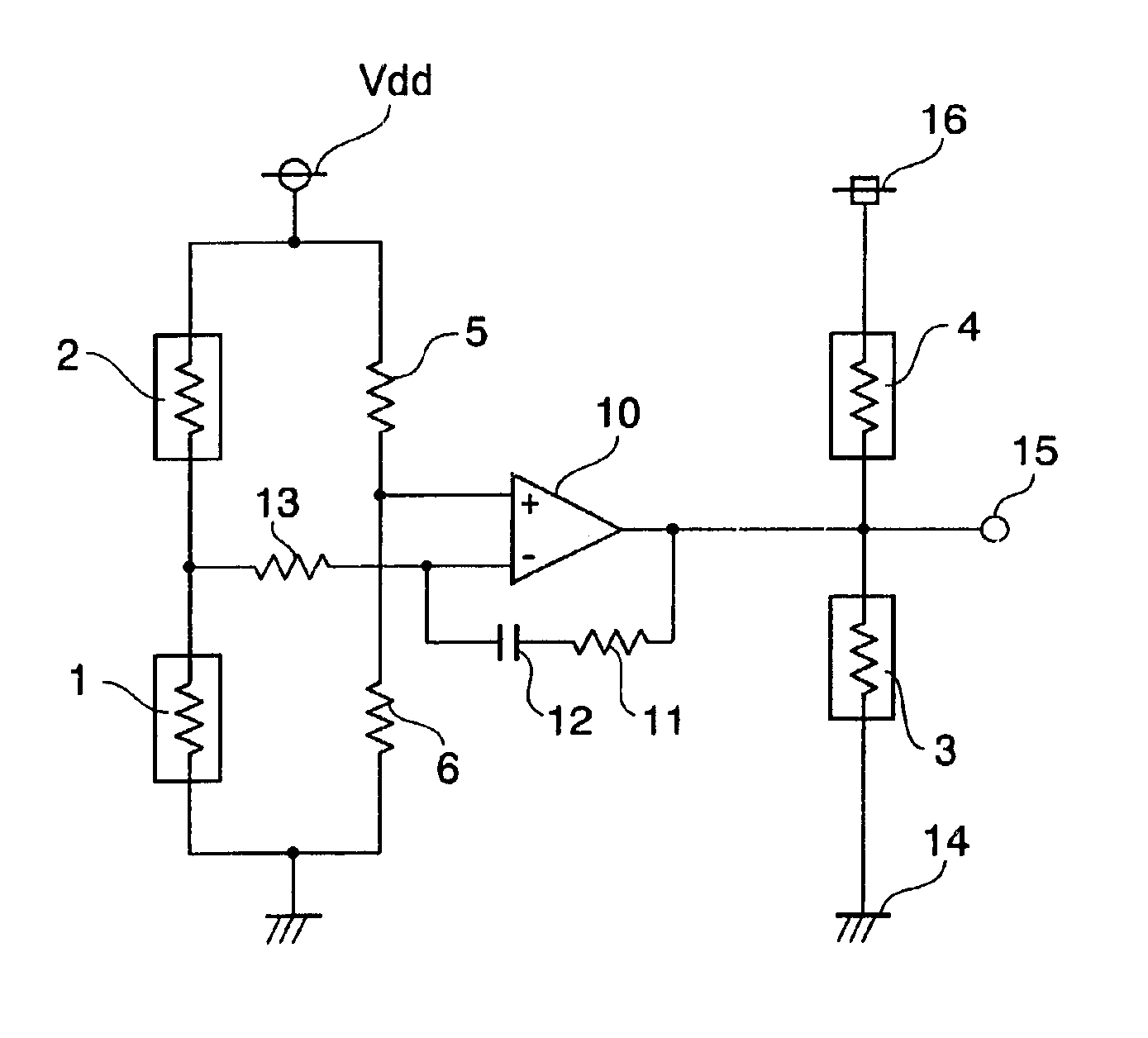
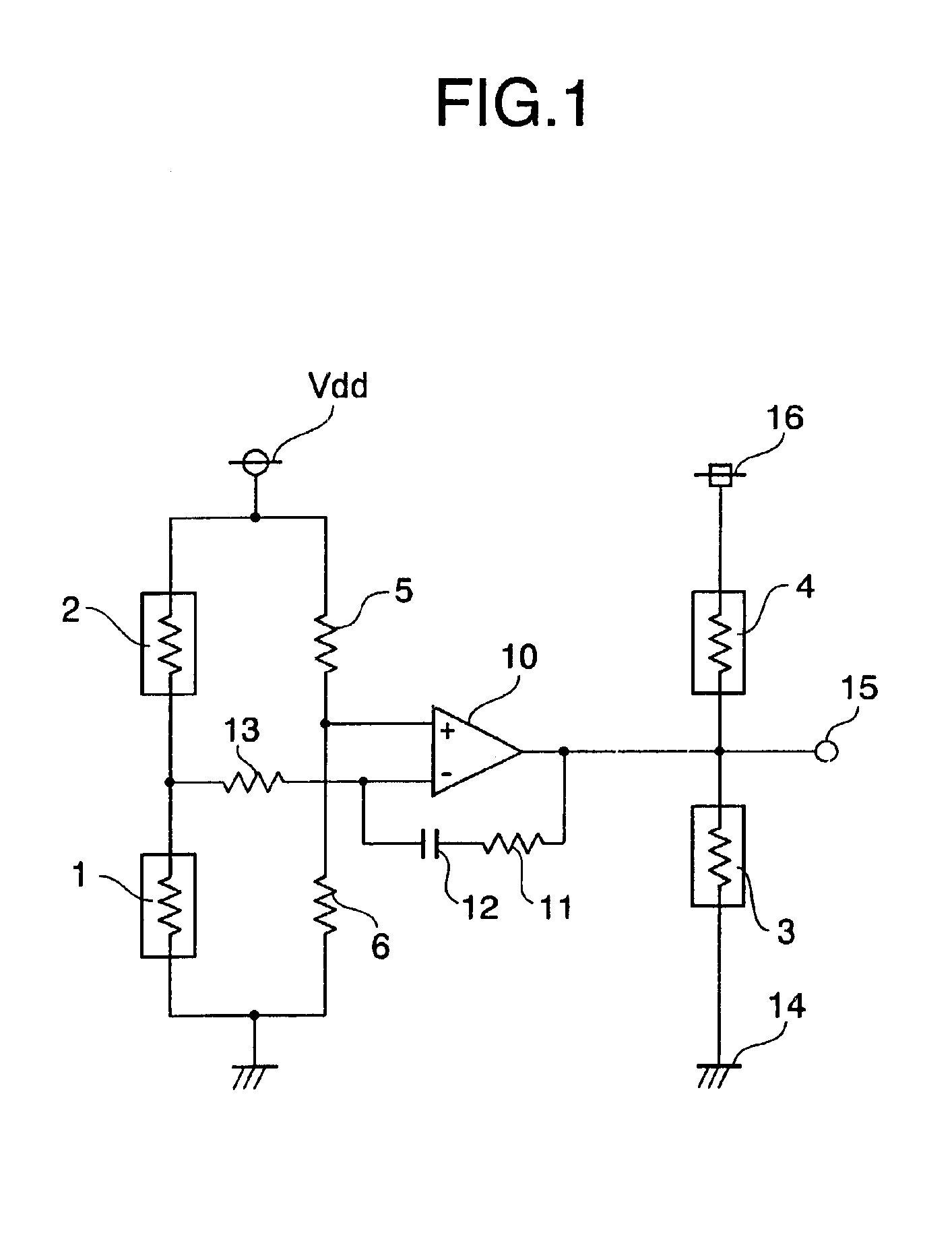
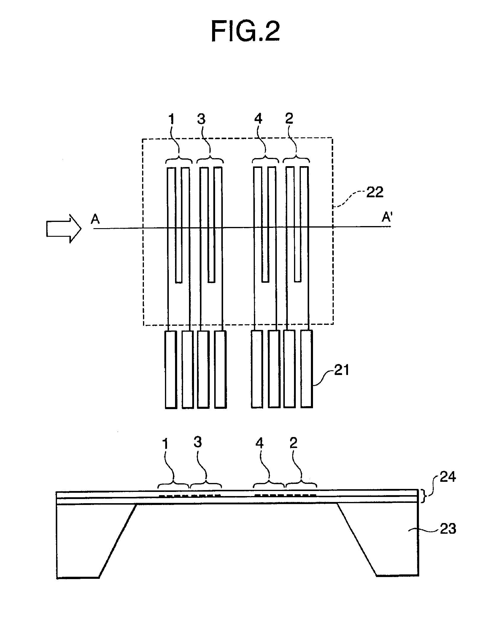
[0035]A thermal type flow rate detector according to a first embodiment of the present invention will hereinbelow be described with reference to FIGS. 1 to 3. FIG. 1 is a circuit diagram showing a configuration of a thermal type flow rate detector according to a first embodiment of the present invention. Note that, in the figures, the same reference numerals denote the same or corresponding constituent elements.

[0036]In FIG. 1, reference numeral 1 denotes an upstream side temperature detecting element; reference numeral 2 denotes a downstream side temperature detecting element; reference numeral 3 denotes an upstream side heat generating element; reference numeral 4 denotes a downstream side heat generating element; reference numeral 5 denotes a fixed resistor; reference numeral 6 denotes a fixed resistor; reference numeral 10 denotes a differential amplifier; reference numeral 11, a fixed resistor; reference numeral 12, a capacitor; reference numeral 13, a fixed resistor; reference...

second embodiment

[0059]A thermal type flow rate detector according to a second embodiment of the present invention will hereinbelow be described with reference to FIGS. 5 and 6. FIG. 5 is a circuit diagram showing a configuration of a thermal type flow rate detector according to a second embodiment of the present invention.

[0060]In FIG. 5, both the circuit and the flow rate detecting elements are the same as those of the above-mentioned first embodiment shown in FIG. 1 except for a fixed resistor 7. The fixed resistor 7 is connected in series with the downstream side heat generating element 4 and between the downstream side heat generating element 4 and the first constant voltage power supply 16 or the output terminal 15.

[0061]Next, the description will hereinbelow be given with respect to the operation of the thermal type flow rate detector according to the second embodiment with reference to FIGS. 5 and 6.

[0062]In the case where temperature drift does not become a problem against the change in flu...

third embodiment

[0069]A thermal type flow rate detector according to a third embodiment of the present invention will hereinbelow be described with reference to FIG. 7. FIG. 7 is a circuit diagram showing a configuration of a thermal type flow rate detector according to a third embodiment of the present invention.

[0070]In FIG. 7, the circuit configuration is the same as that of the above-mentioned first embodiment shown in FIG. 1 except for a fixed resistor 8, and is given a temperature compensation method different from that of the above-mentioned second embodiment.

[0071]In this embodiment, the fixed resistor B is connected in parallel with the temperature detecting element 1, whereby in order to compensate for the outward reduction of the temperature coefficient of the upstream side temperature detecting element 1, the upstream side temperature detecting element 1 is operated so as to be largely changed for the fluid temperature than the downstream side temperature detecting element 2.

[0072]For e...


PUM


Abstract

A thermal type flow rate detector includes: a bridge circuit constructed by upstream side and downstream side temperature detecting elements for detecting a temperature of fluid flowing from the upstream side to the downstream side, and fixed resistors; and a temperature difference controlling circuit for continuously supplying an electric power to upstream side and downstream side heat generating elements so that a temperature difference between the temperature detecting elements becomes a predetermined value. The temperature difference controlling circuit includes: a differential amplifier connected to the bridge circuit; a first constant voltage power supply; a second constant voltage power supply having a lower constant voltage than that of the first constant voltage power supply; and the upstream side and downstream side heat generating elements.

Description

BACKGROUND OF THE INVENTION[0001]1. Field of the Invention[0002]The present invention relates in general to a thermal type current meter or a thermal type flow meter for detecting a flow velocity or a flow rate of gas or liquid, for example. In particular, the invention relates to a thermal type flow rate detector which is used to detect a quantity of air sucked into an engine for an automobile or the like as an example of application, and which is capable of enhancing the detection accuracy.[0003]2. Description of the Related Art[0004]In general, as for a flow rate detector for measuring a quantity of air sucked into an engine for an automobile, a thermal type one is generally used which can detect a mass flow rate, and which is excellent in cost performance. An engine sucks thereinto air on the basis of the reciprocating motion of a piston and increases or decreases a quantity of sucked air by opening or closing a throttle valve. The pulsation amplitude of air sucked into a 4-cyli...

Claims


Application Information

Patent Timeline
Patent Type & Authority Patents(United States)
IPC IPC(8): G01F1/696G01F1/684G01F1/699G01F1/698F02D45/00G01F1/68
CPCG01F1/699G01F1/6845G01F1/68
Inventor TANIMOTO, KOJISUETAKE, NARUKI
Owner MITSUBISHI ELECTRIC CORP
Why Eureka
Try Eureka