
Pressure sensing device for rheometers

Inactive Publication Date: 2005-05-17
RHEOSENSE
View PDF12 Cites 32 Cited by
  • Summary
  • Abstract
  • Description
  • Claims
  • Application Information

AI Technical Summary

Benefits of technology

[0010]According to the invention, surface roughness on a rheometer plate can be substantially eliminated by providing a rheometer plate with monolithically integrated pressure transducers. The plate forms a single substantially smooth surface against which the liquid generating the pressure to be measured acts. With such arrangement, accuracy of normal stress difference measurement depends only on transducer resolution, not on the size of plate. This also allows the employment of a smaller plate for normal stress difference measurements. With a smaller plate, higher shear rates can be accessed due to a deterred onset of flow instability by smaller centrifugal force and a lower tendency to fracture. Also, a smaller amount of sample is required.
[0016]The rheometer plate of the invention may be used as the stationary plate in conjunction with a rotating cone for generating the shear to be measured or may be used as a wall of a passage in a slit rheometer device. In addition, the invention also includes a novel miniature slit rheometer device having a slit or flow passage with a plurality of steps to provide varying dimensions so that exact viscosity can be measured using a single device rather than having to switch between two or more devices.
[0017]The rheometer plate can include a proximity or distance sensor to electronically detect the position of the cone with respect to the plate so that the point of contact does not need to be measured separately. Such sensor can further continuously monitor the position of the cone during measurement, which will improve greatly the accuracy of measurement.
[0018]The primary object of present invention is to provide a rheometer plate with pressure sensors integrated monolithically in order to eliminate the step of mounting individual pressure transducers or a strip of pressure transducers as is necessary in past practice. This provides a smooth surfaced plate that does not affect the pressure exerted by the liquid against the plate. Furthermore, the miniaturization of the pressure measuring sensors allows the miniaturization of the rheometer plate. On-chip or near on-chip read-out circuits, analog to digital converters (ADC), input / output interfaces (I / O) for communication with a host process controller, and, if desired, telemetry circuits for wireless communication with a host process controller, may be provided to enhance the measurement accuracy by minimizing the noise to signal ratio. Temperature sensors may be included in the rheometer plate to measure temperature changes, and multiple temperature sensors can be arranged to measure temperature gradients along the plate. In addition, a proximity sensor may be included in the rheometer plate to detect and continuously monitor the gap between the rheometer plate and the cone. Additional on-chip data analysis circuits and systems may also be provided.

Problems solved by technology

However, with this method, the deflection of the spring results in a change of the gap between the stationary plate and the rotating cone.
The stiff spring, however, requires a very elaborate detection circuit for accurate detection of small deflection.
However, the finite response time of the feedback control of the servo system is a source of uncertainty especially under a dynamic control system.
However, it is generally impossible to remove such surface roughness completely with sensors individually mounted in the surface, so some effect from the roughness will always be present.
Current rheometers, however, do not provide any mean to monitor the position of the cone during measurement.
However, relatively complex sensors are required to measure deflection at a plurality of regions on the membrane or to separate measurements made by several sensors in the same recess measuring different regions of the membrane.

Method used


Image

  • Pressure sensing device for rheometers
  • Pressure sensing device for rheometers
  • Pressure sensing device for rheometers

Examples


Embodiment Construction

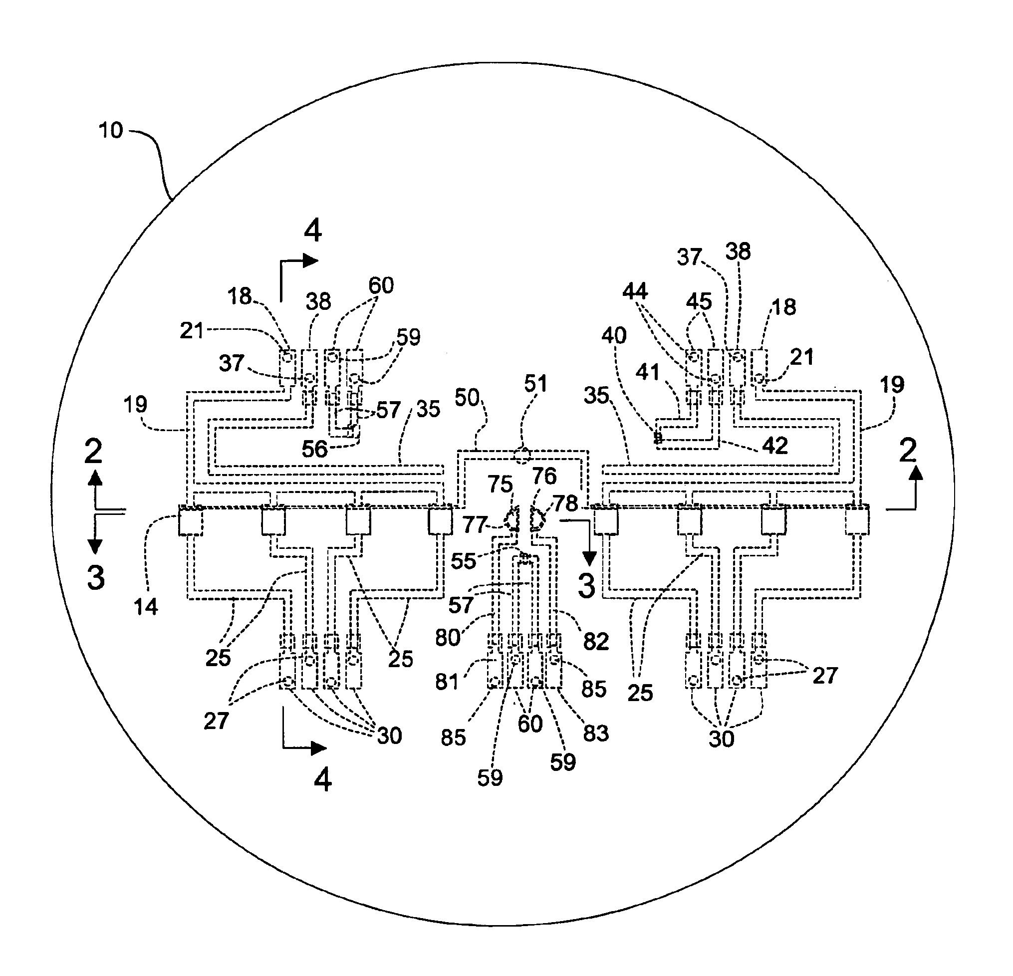
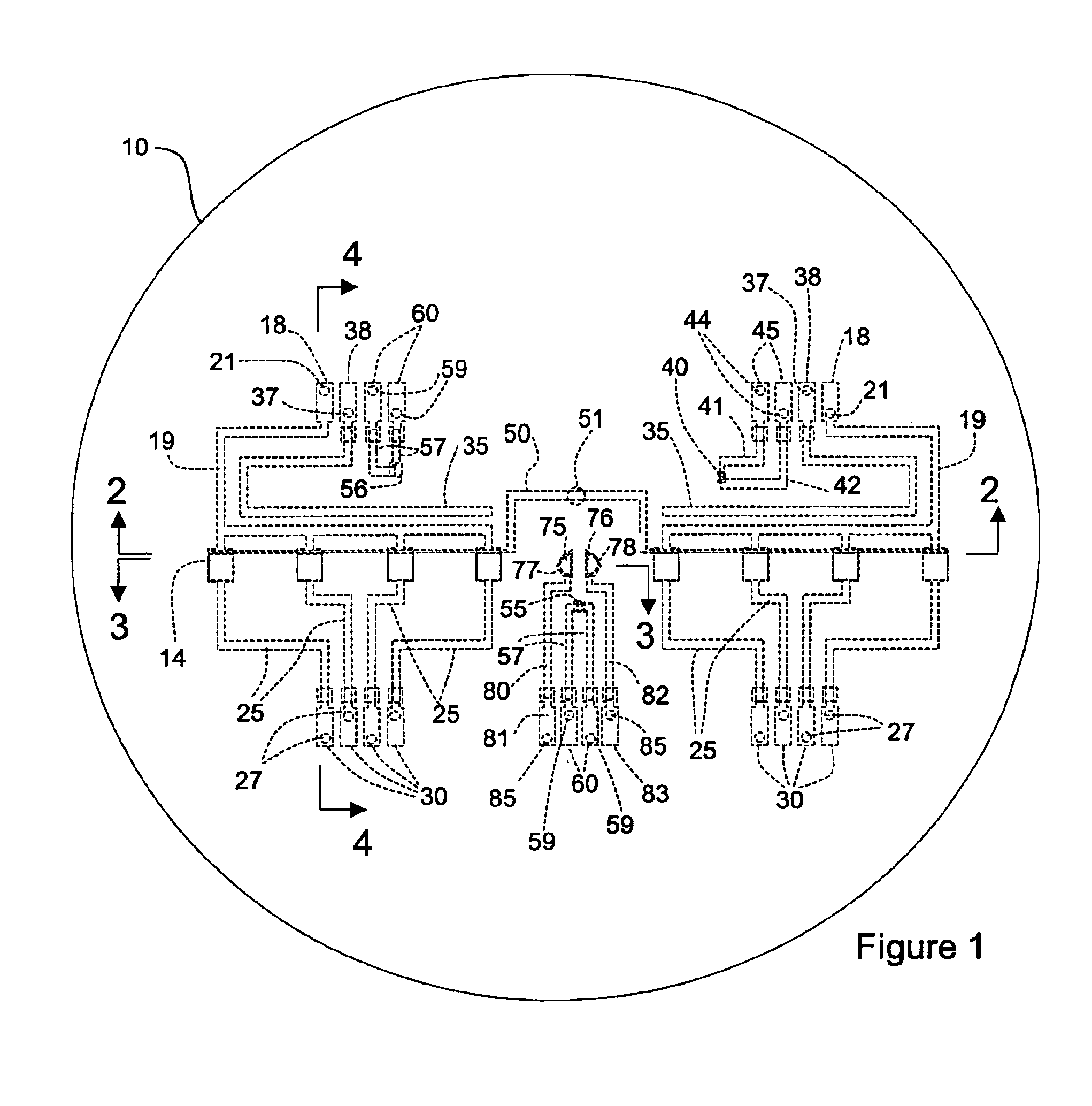
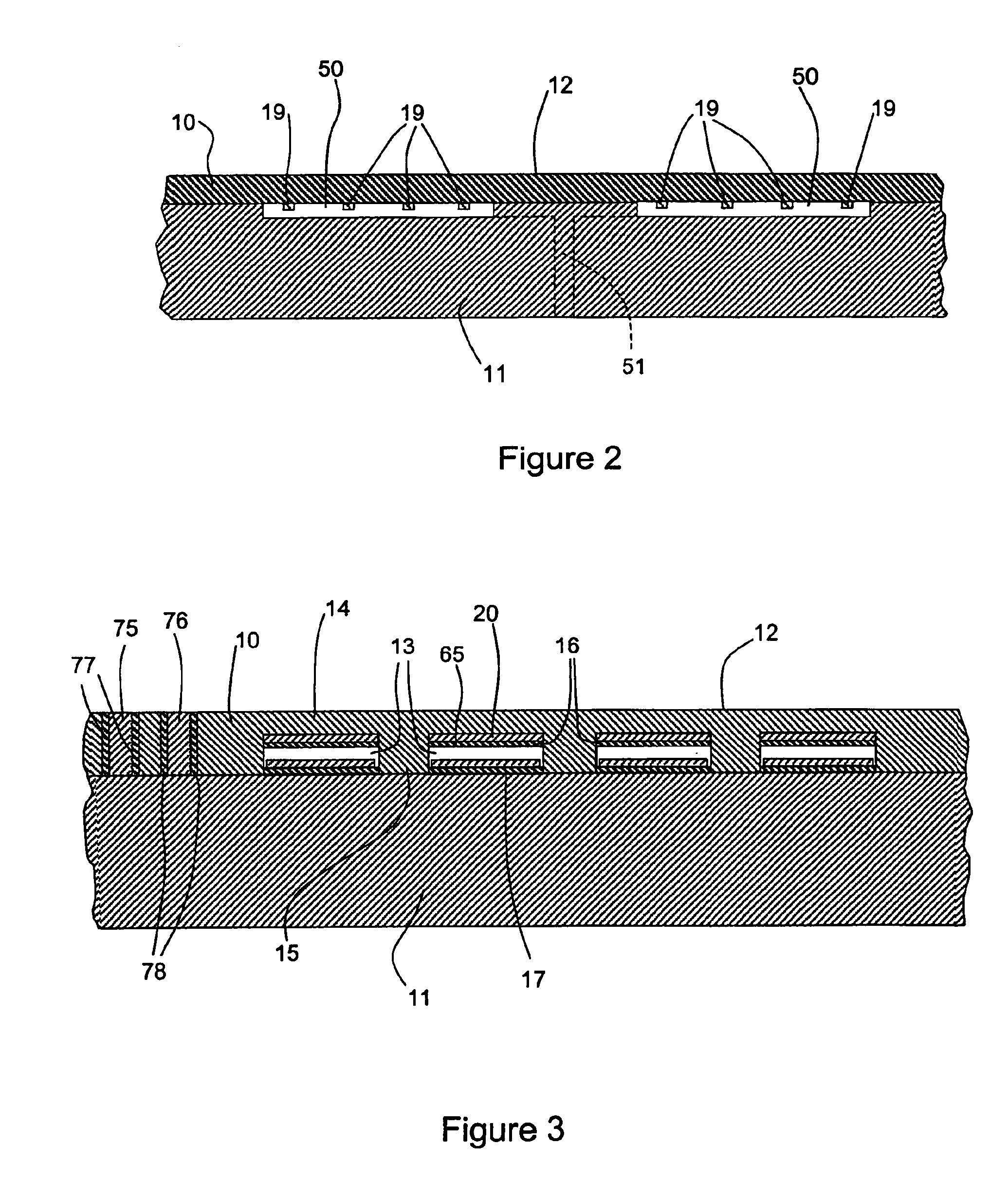
[0035]In order to measure the local pressure of a liquid under well-defined unperturbed states for measuring accurate normal stress differences, it is desirable to have a smooth rheometer plate against which the liquid acts and which has a plurality of pressure sensors spaced in the plate to measure pressure at the locations of the pressure sensors. To provide a smooth surface against which the liquid can act, a rheometer plate according to the invention is constructed using a membrane, such as formed by a silicon wafer, to maintain the smooth surface of the plate, and includes monolithically integrated pressure sensors. Various types of pressure sensors may be used, such as capacitive pressure sensors. An embiodment of the rheometer plate of the invention with capacitive pressure sensors is shown in FIGS. 1-6. The monolithically constructed plate comprises a top wafer or membrane 10, FIGS. 2, 3, and 4, and a bottom wafer or substrate 11. The top membrane 10 is preferably a silicon ...


PUM


Abstract

An improved rheometer plate includes a smooth sensing surface with monolithically integrated miniature pressure sensors which do not interfere with the smooth surface. Pressure sensing diaphragms formed by the smooth surface deflect in response to local pressures against the surface to enable the measurement of unperturbed local pressures of materials sheared between plates. The pressure sensors are sufficiently small that measured pressures are considered to be significantly local properties compared to the size of the plate. Normal stress differences and viscosity of fluid are measured accordingly. The membrane covers a plurality of wells or recesses with pressure sensors located in the wells to measure the deflection of the membrane over the wells. Capacitive or other sensors may be used. The rheometer plate can be used as part of a slit rheometer with a slit of varying dimensions.

Description

RELATED APPLICATION[0001]This application claims the benefit of provisional Application Ser. No. 60 / 335,375 filed Oct. 31, 2001, and titled “Pressure Sensing Device For Rheometers”.BACKGROUND OF THE INVENTION[0002]1. Field[0003]This invention is in the field of pressure measurement devices and particularly devices such as rheometer plates for measuring local pressures of fluids during shear and restricted flow.[0004]2. State of the Art[0005]Normal stress differences and viscosities are important properties of plastics and other liquids that need to be characterized and taken into account for the efficient processing of these liquids. One way to measure normal stress differences is to measure the local pressure of the fluid under shear conditions against a rheometer plate. Fluid is sheared between one stationary plate and a rotating cone or plate. The stationary plate is connected to a spring, which deflects in response to the normal stress difference of the liquid being sheared. How...

Claims


Application Information

Patent Timeline
IPC IPC(8): G01L13/02G01L7/02G01N11/10G01L13/00G01L7/08G01N11/14G01N11/00G01L9/00G01L15/00G01L19/04G01M13/02G01N11/08
CPCG01L9/0042G01L9/0073G01L9/0079G01L19/0092G01M13/022G01N11/08G01L15/00G01F1/38G01L7/00G01L7/08G01L13/02
Inventor BAEK, SEONG-GI
Owner RHEOSENSE
Learn More