XRR detector readout processing

a detector and readout technology, applied in the field of analytical instruments, can solve the problems of inability to resolve the energy or number of incident x-ray photons, the detection of the inability to generally detect high-order fringes at higher incidence angles. achieve the effect of accurate determination of these properties, enhanced spatial resolution, and high dynamic rang

Inactive Publication Date: 2005-05-17
BRUKER TECH LTD
View PDF6 Cites 13 Cited by
  • Summary
  • Abstract
  • Description
  • Claims
  • Application Information

AI Technical Summary

Benefits of technology

[0012]It is still a further object of some aspects of the present invention to provide systems for X-ray microanalysis with enhanced spatial resolution.
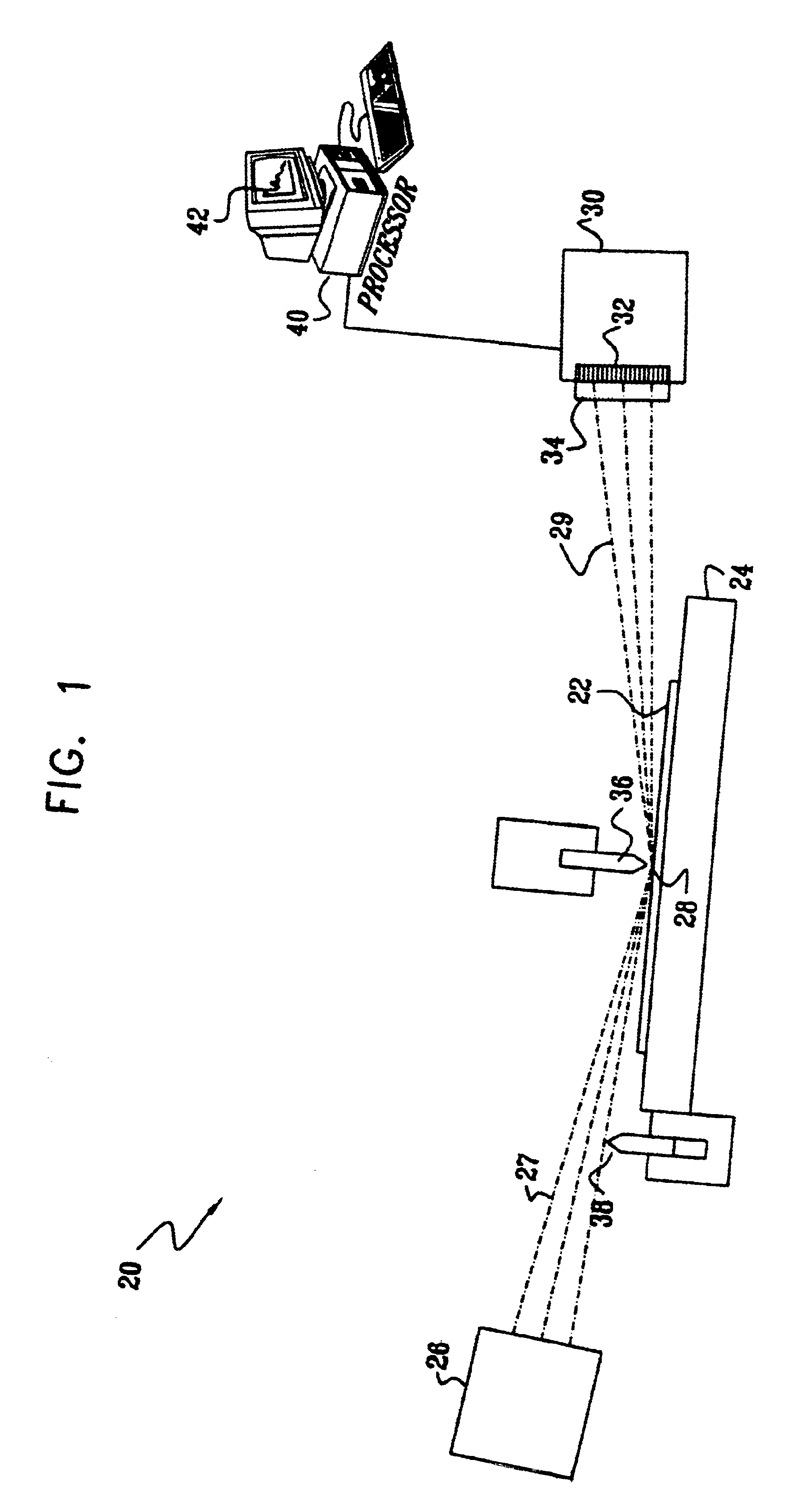
[0013]In preferred embodiments of the present invention, a system for X-ray reflectometry is used to determine properties of thin films on the surface of a sample, typically a semiconductor wafer. The sample is irradiated by a monochromatic beam of X-rays, which is focused to a small spot size on the surface of the sample. X-rays reflected from the surface are incident on a detector array, preferably a CCD array, each detector element in the array corresponding to a different angle of reflection from the surface. Charge stored by the detector elements is clocked out of the array to a processor, which analyzes the charges to derive a fringe pattern, corresponding to the intensity of X-ray reflection from the surface as a function of angle. The X-ray optics and processing circuitry in the system are arranged to achieve a high dynamic range, whereby high-order fringes are plainly apparent in the reflected signal. The processor analyzes the fringe pattern based on a physical model of thin film properties, including density, thickness and surface roughness. The high dynamic range enables the system to determine these properties accurately not only for the upper thin film layer, but also for one or more underlying layers on the surface of the sample.
[0014]As noted in the Background of the Invention, one of the major problems in X-ray reflectometry systems is that surface reflectivity is much greater at low angles (near 0°) than at higher angles. The strong flux of low-angle X-rays that is incident on the detector array tends to increase the overall background level, making it difficult to detect the weaker high-angle flux. To address this problem, in some preferred embodiments of the present invention, the system comprises a dynamic shutter, having low-angle and high-angle detection positions. In the low-angle position, the shutter allows the entire beam of X-rays from the X-ray source to impinge on the sample. In the high-angle position, however, the shutter blocks low-angle X-rays. As a result, the intense low-angle reflections are eliminated, so that the background level at the detector is reduced, and useful signals can be derived at high angles. The processor “stitches together” the signals received by the detector in the low- and high-angle positions of the shutter in order to derive a single fringe spectrum with enhanced dynamic range.
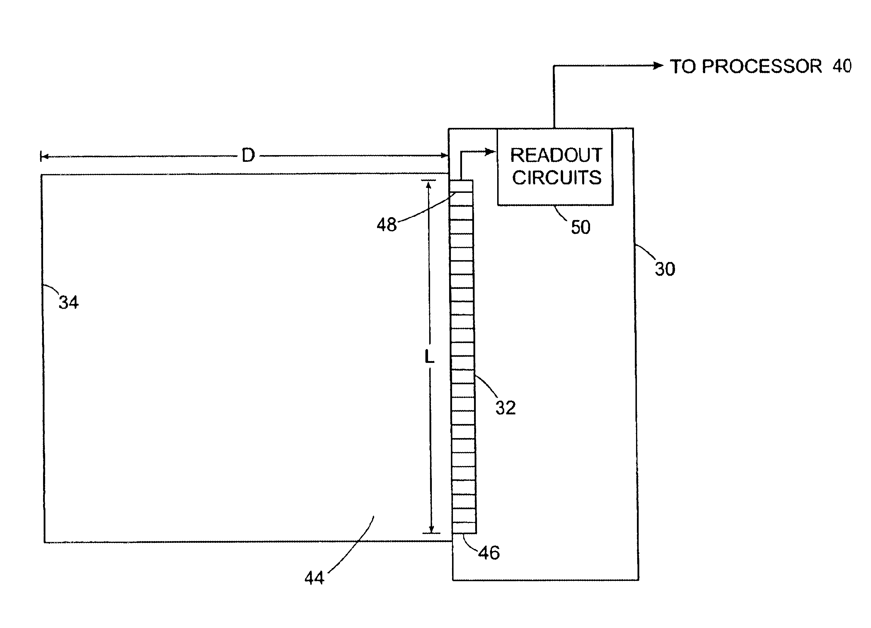
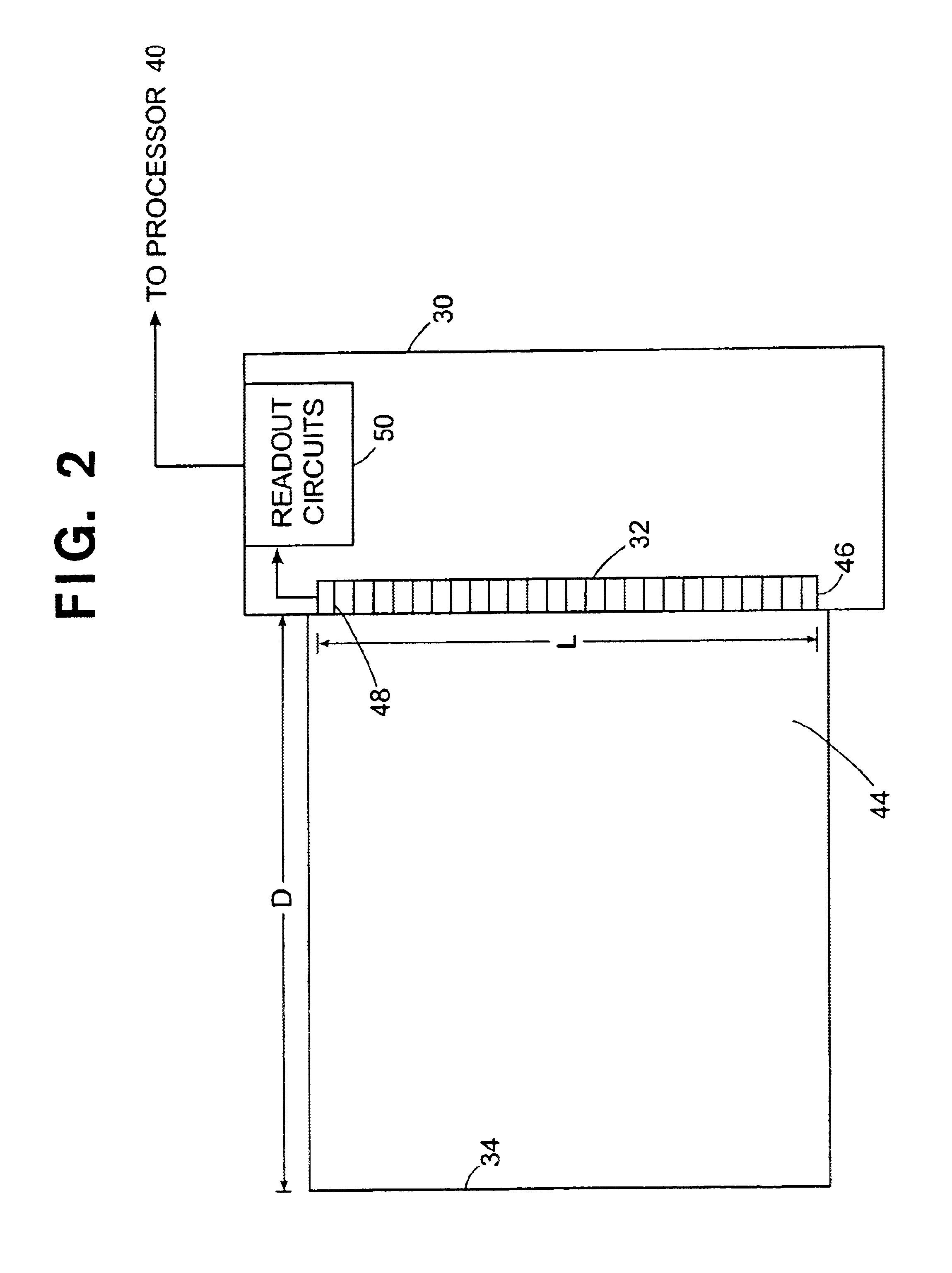
[0015]Preferably, the housing and readout circuits associated with the detector array are also designed to reduce the background level in the high-angle elements. Most preferably, the CCD array is coupled to the readout circuits so that the signal output from the array to the circuits is adjacent to the end of the array that receives the high-angle reflections. In this configuration, the high-angle array elements are read out first, giving accurate readings of the weak signals received by these elements before the readings are contaminated by background charge transferred from the low-angle elements. Additionally or alternatively, the detector array is protected by an evacuated enclosure, closed off by an X-ray transparent window spaced a substantial distance in front of the array, between the array and the sample. As a result, scattering of low-angle X-rays from the window and from the air in the space immediately in front of the array is substantially reduced, thus further reducing the background level at the high-angle elements.
[0016]As a further means for reducing both the size of the incident X-ray spot on the surface of the sample and the excessive signal at low incidence angles, in some preferred embodiments of the present invention, a dynamic knife edge is positioned over the surface. Preferably, the dynamic knife edge is operated in conjunction with the above-mentioned dynamic shutter. For measurements at low incidence angles, the knife edge is lowered very near to the surface, intercepting the incident X-ray beam and thus shortening the lateral dimension of the spot on the surface (i.e., the dimension in the direction along the surface that is roughly parallel to the beam axis). For high-angle measurements, at which the dynamic shutter is used, the knife edge is preferably raised out of the way, to allow the full intensity of the X-ray beam to be used. Such operation of the knife edge allows measurements to be made with high spatial resolution, particularly-at low angles at which the lateral dimension of the spot is most greatly elongated, while maintaining high sensitivity even at high angles.
[0017]In some preferred embodiments of the present invention, the processor analyzes the detector array output so-as to determine a total, lumped X-ray flux for each detector element at high intensities (typically at low angles), while effectively counting individual X-ray photons per element at low intensities (high angles). The inventors have found that an X-ray photon of a known energy will generate a certain average charge in a detector element when the photon is incident as part of a high photon flux, and a lower average charge, which may be spread over two adjacent detector elements, at low flux. Preferably, to analyze the array output, the processor first determines the number of photons incident on each detector element that encountered a high X-ray flux, by dividing the total charge accumulated in these elements by the high-flux average charge. Then, over the remaining detector elements, the processor seeks individual elements or pairs of elements having charge levels comparable to the low-flux charge. The processor records a single photon count for each such element or pair of elements. This technique allows a single detector array, such as a CCD array, to be used simultaneously for both lumped flux and photon counting measurements, thus further enhancing the dynamic range with which the system can measure the pattern of reflection fringes.

Problems solved by technology

Typically, each element accumulates photoelectric charge over a period of time before being read out and therefore cannot resolve the energy or number of incident X-ray photons.
Consequently, high-order fringes at higher incidence angles cannot generally be detected.
A further drawback of X-ray thin film measurement systems known in the art is their lack of spatial resolution.

Method used


Image

  • XRR detector readout processing
  • XRR detector readout processing
  • XRR detector readout processing

Examples


Embodiment Construction

[0071]FIG. 1 is a schematic illustration of a system 20 for X-ray reflectometry of a sample 22, in accordance with a preferred embodiment of the present invention. The sample is preferably mounted on a motion stage 24, allowing accurate adjustment of its position and orientation. An X-ray source 26, typically an X-ray tube with suitable monochromatizing optics (not shown), irradiates a small area 28 on sample 22. A preferred X-ray tube for this purpose is the XTF5011 tube, produced by Oxford Instruments of Scotts Valley, Calif. A number of different optical configurations that may be used in source 26 are described in U.S. patent application Ser. No. 09 / 408,894, which is assigned to the assignee of the present patent application and is incorporated herein by reference. The optics preferably comprise a curved crystal monochromator, such as the Doubly-Bent Focusing Crystal Optic, produced by XOS Inc., of Albany, N.Y. Other suitable optics are described in patent application Ser. No. 0...


PUM

PropertyMeasurementUnit
diameteraaaaaaaaaa
energyaaaaaaaaaa
reflection anglesaaaaaaaaaa

Abstract

Reflectometry apparatus includes a radiation source, adapted to irradiate a sample with radiation over a range of angles relative to a surface of the sample, and a detector assembly, positioned to receive the radiation reflected from the sample over the range of angles and to generate a signal responsive thereto. A shutter is adjustably positionable to intercept the radiation, the shutter having a blocking position, in which it blocks the radiation in a lower portion of the range of angles, thereby allowing the reflected radiation to reach the array substantially only in a higher portion of the range, and a clear position, in which the radiation in the lower portion of the range reaches the array substantially without blockage.

Description

CROSS-REFERENCE TO RELATED APPLICATIONS[0001]This patent application is a continuation of U.S. application Ser. No. 10 / 300,504, filed Nov. 20, 2002, and entitled “X-RAY REFLECTOMETER” now U.S. Pat. No. 6,639,968, which is a continuation of U.S. application Ser. No. 09 / 833,902 (now U.S. Pat. No. 6,512,814 B2), filed Apr. 12, 2001, and entitled “X-RAY REFLECTOMETER”, the contents of which are incorporated herein by reference in their entirety.FIELD OF THE INVENTION[0002]The present invention relates generally to analytical instruments, and specifically to instruments and methods for thin film analysis using X-rays.BACKGROUND OF THE INVENTION[0003]X-ray reflectometry (XRR) is a well-known technique for measuring the thickness, density and surface quality of thin film layers deposited on a substrate. Conventional X-ray reflectometers are sold by a number of companies, among them Technos (Osaka, Japan), Siemens (Munich, Germany) and Bede Scientific Instrument (Durham, UK). Such reflectom...

Claims


Application Information

Patent Timeline
Patent Type & Authority Patents(United States)
IPC IPC(8): G01N23/20G01N23/22G01N23/223G01B15/02G01T1/36
CPCG01T1/36
Inventor YOKHIN, BORISDIKOPOLTSEV, ALEXANDERMAZOR, ISAACBERMAN, DAVID
Owner BRUKER TECH LTD
Why Eureka
Try Eureka