Small diameter, high strength optical fiber

a technology of optical fibers and small diameters, applied in the field of silicon optical fibers, can solve the problems of reducing the mechanical strength of optical fibers, limited space to accommodate large diameter fibers, and common fiber damage, and achieves the effects of reducing the time needed, high strength, and high tolerance to bending stresses

Inactive Publication Date: 2005-05-17
3M INNOVATIVE PROPERTIES CO
View PDF28 Cites 29 Cited by
  • Summary
  • Abstract
  • Description
  • Claims
  • Application Information

AI Technical Summary

Benefits of technology

[0014]The present invention satisfies the need for a small diameter, mechanically strong, coated optical fiber using a silica-clad, silica fiber coated with a permanent polymeric layer to a total diameter from about 120 microns to about 160 microns. A preferred embodiment of a coated optical fiber has a silica clad silica core drawn to a diameter of 80-85 microns before in-tower application of one or more permanent coatings that contribute to a finished optical fiber diameter of about 125 microns. The resulting coated optical fiber shows resistance to stress corrosion, and surprisingly exhibits high strength as measured by standard test method FOTP-28 (dynamic fatigue). Cleavable optical fibers, processed according to the present invention, readily interface with a number of standard fiber optic connectors, without stripping, to provide connections wherein the optical fiber has a high tolerance to bending stresses. This provides a useful benefit by decreasing the time needed to join an optical fiber to a suitable connector. The lack of a stripping step also enhances optical fiber reliability, because there is no need to expose the bare glass of the fiber to make a connection. Additional reliability for coated optical fibers according to the present invention accrues from polymerizing the permanent polymeric coating of a GGP fiber using a photoinitiator that does not produce potentially corrosive byproducts. In the absence of corrosive byproducts a coated optical fiber retains its strength for use in applications that include exposure to humid conditions at elevated temperature.

Problems solved by technology

In many optoelectronic devices and optical fiber containment structures, there is limited space to accommodate large diameter fibers that include primary and secondary coated layers, as described above.
Fiber damage commonly occurs during the stripping process to remove buffer coating from an optical fiber.
It is known that fluorine containing resin coatings cause reduction of the mechanical strength of optical fibers compared with similar optical fibers coated using resins that contain no fluorine.
Although including materials and coating methods, this patent (U.S. Pat. No. 5,181,269) provides no supportive data related to optical fiber strength.
The mechanical properties and lifetime of a coated optical fiber may be adversely affected by inappropriate selection of a photoinitiator to cure polymeric fiber coatings.
Unfortunately, high temperature and high humidity conditions are relatively common during operation of vehicles including submarines and related naval craft, space craft, aircraft, and other applications that currently use, or have the potential to use, optical fibers and related devices.

Method used


Image

  • Small diameter, high strength optical fiber
  • Small diameter, high strength optical fiber

Examples


examples

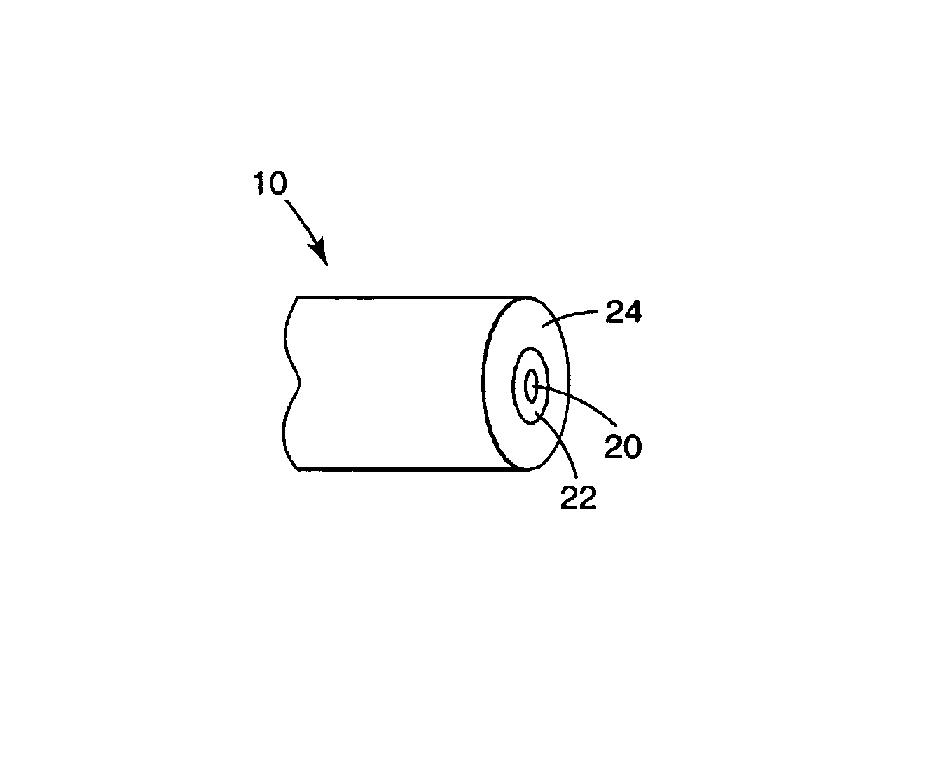
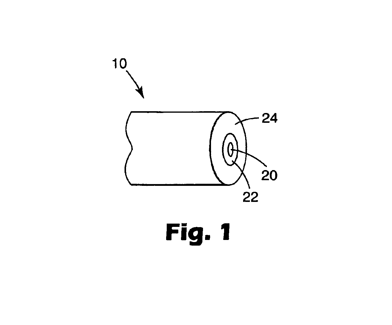
[0057]Table 1 provides Comparative Examples of coated optical fiber prepared using a similar process to that used for optical fibers of Examples according to the present invention shown in Table 2. Both tables include information indicating diameters for silica clad optical fibers, thickness of coatings applied thereto, and the total diameters of coated optical fibers.

examples 1a-1c

[0061]Examples 1A-1C represent coated optical fibers, having a diameter of about 160 microns, prepared using separate runs of material under substantially the same draw tower conditions. The polymer (P-coat) coating used for Example 1A and Example 1B was an epoxy resin cured using a cationic photoinitiator having a hexafluoroantimonate anion. An iodonium methide photoinitiator was used to cure the polymer coating of Example 1C. In each case the P-coat was overcoated with an acrylated urethane coating identified as DSM 3471-2-136 (available from DSM Desotech, Elgin, Ill.) that cures by a radical polymerization mechanism. Dynamic fatigue (tensile to failure as in FOTP-28) of Examples 1A and 1B gave results showing reasonable consistency from about 49.2×10³ kg / cm2 (700 kpsi) to about 52.7×10³ kg / cm2 (750 kpsi). Example 1C gave consistent, improved performance close to 56.2×10³ kg / cm2 (800 kpsi). Example 1C differs from the others only in the use of bis(dodecylphenyl) iodonium methide p...

examples 2a-2d

[0062]Examples 2A-2D represent coated optical fibers, having a diameter of about 130 microns, prepared using separate runs of material under substantially the same draw tower conditions. The polymer (P-coat) coating was an epoxy resin cured using a cationic photoinitiator having a methide anion. This was overcoated with an acrylated urethane coating that cures by a radical polymerization mechanism. Dynamic fatigue (tensile to failure as in FOTP-28) of multiple samples of Examples 2A-2D showed highest consistency and strength with results close to 56.2×10³ kg / cm2 (800 kpsi).


PUM

PropertyMeasurementUnit
diameteraaaaaaaaaa
diameteraaaaaaaaaa
diameteraaaaaaaaaa

Abstract

A coated optical fiber, preferably a GGP optical fiber includes an optical fiber core, and a silica cladding over the optical fiber core, to provide a silica clad core. A permanent polymeric coating forms on the silica cladding during ultraviolet radiation of a photocurable composition containing a non-hydrolyzable photoinitiator. The coated optical fiber has a diameter from about 120 microns to about 160 microns and a relative frequency distribution of at least about 85% for dynamic fatigue measurements between about 49.2×10³ kg/cm2 (700 kpsi) and about 63.3×10³ kg/cm2 (900 kpsi).

Description

FIELD OF THE INVENTION[0001]The invention relates generally to silica optical fibers, and more specifically to thin, permanently coated optical fibers having a small average diameter yet possessing strength comparable to conventional optical fibers.BACKGROUND OF THE INVENTION[0002]Modern communications networks have been constructed to supply and share almost incomprehensible amounts of information. Regardless of the current capabilities of communications systems, there is a demand for more information and communication services. This demand could be satisfied using additional signal carriers, i.e. optical fibers. Each additional carrier adds to the space required for forming connections between optical fibers and related optoelectronic devices. This is contrary to the prevailing trend for succeeding generations of signal carriers to occupy less space than current systems.[0003]The manufacturing process for optical fibers requires the fabrication of a pre-form, including a wave-guid...

Claims


Application Information

Patent Timeline
Patent Type & Authority Patents(United States)
IPC IPC(8): C03C25/10G02B6/02G02B6/44C03C25/24C08F2/50
CPCG02B6/02395C03C25/106
Inventor WALKER, JR., CHRISTOPHER BLANDLAUMER, JAMES W.MARKLUND, JESPER KARL
Owner 3M INNOVATIVE PROPERTIES CO
Why Eureka
Try Eureka