Cardiac valve procedure methods and devices

a heart valve and valve technology, applied in the field of cardiac valve procedure methods and devices, can solve the problems of one effective treatment for patients with aortic stenosis, substantial and invasive undertaking for patients, and little progress in the development of safer and less invasive valve delivery systems. , to achieve the effect of reducing the risk of heart failure and reducing the risk of emboli

Inactive Publication Date: 2005-05-24
MEDTRONIC INC
View PDF68 Cites 654 Cited by
  • Summary
  • Abstract
  • Description
  • Claims
  • Application Information

AI Technical Summary

Benefits of technology

[0013]The temporary filter acts to prevent emboli that may be dislodged during the valve procedure from moving distal to the filter. In a preferred method of use, the filter is placed in the aorta proximal to the braciolcephalic artery to prevent emboli from reaching the brain. The filter can be one of a variety of designs, including, but not limited to a mesh filter with a pore size smaller than the dimensions of anticipated embolic particles. The filter can be inserted directly into the aorta or advanced into the aorta from a peripheral artery. It is preferably inserted in a compressed state and expands or is expanded to a larger state at a desired site within the aorta.
[0016]Another aspect of the present invention is a method of performing a procedure on a beating heart involving, at a minimum, inserting into the aorta, a temporary valve, as described above, removing at least some portion of the native aortic valve, and placing a permanent valve prosthesis at a site within the aorta. The temporary valve allows removal of the native valve while reducing the risk of heart failure due to insufficiency of the native valve. Removal of at least some portion of the native valve can be carried out with one or a variety of tools that can be inserted either directly into the aorta or through a peripheral artery and advanced to the native valve. Similarly, the permanent valve prosthesis can be inserted either directly into the aorta or advanced into the aorta from a peripheral artery. The valve prosthesis is preferably inserted in a compressed state and expands or is expanded at the desired implantation site. The implantation site is preferably proximal to the coronary arteries, but can be at any suitable location in the aorta. The valve can be one of a variety of types known in the art, but is preferably a flexible valve suitable for inserting into an artery in a compressed state. This method can further involve the placement of a temporary filter as described above to reduce the risk of emboli generated during manipulation of the native valve. As described above, the temporary filter can be a separate device or an integral component of the temporary valve.

Problems solved by technology

Currently, there is only one effective treatment for patients with aortic stenosis—aortic valve replacement via open heart surgery.
Unfortunately, this is a substantial and invasive undertaking for the patient.
While there have been significant advances in heart valve technology over the last thirty years, there has been little progress in the development of safer and less invasive valve delivery systems.
This procedure is accompanied by a 5% mortality rate, in addition to significant morbidity (stroke, bleeding, myocardial infarction, respiratory insufficiency, wound infection) related to the use of cardiopulmonary bypass and the approach to the aortic valve.
Elderly patients and those who require concomitant coronary artery bypass grafting experience increased morbidity and mortality.
Using the technology available at that time, success was limited.
These approaches still require cardiopulmonary bypass and cardiac arrest, which entail significant morbidity and a prolonged postoperative recovery.
Although there has been great progress in the treatment of coronary artery disease without cardiopulmonary bypass (angioplasty / stenting and “off-pump” coronary artery bypass grafting), similar advances have not yet been realized in heart valve surgery.
There are three significant challenges to replacing a diseased aortic valve without cardiopulmonary bypass.
When the valve becomes acutely and severely incompetent during removal, the patient develops heart failure leading to death unless the function of the valve is taken over by another means.
First, they tend to occupy a significant length of the vessel when deployed.
The valves disclosed to date tend also to be rather flimsy and may have difficulty supporting the fluid pressures while the valve is closed.
A more significant disadvantage of these valves is that they generally must be inserted into a vessel at a significant distance from the valve to allow adequate room for deployment.
This adds morbidity and complexity to the procedure.
Another drawback of the prior art is that valves with three or fewer leaflets rely on the perfect performance of each of those leaflets.
If one of the leaflets malfunctions, the valve fails to function adequately.

Method used


Image

  • Cardiac valve procedure methods and devices
  • Cardiac valve procedure methods and devices
  • Cardiac valve procedure methods and devices

Examples


Embodiment Construction

[0053]The methods and devices of the present invention can be used for performing procedures on cardiac valves without cardiac arrest or cardiopulmonary bypass. Various embodiments of the methods and devices are described to clarify the breadth of the present invention.

Preferred Embodiments—Temporary Filter Device

[0054]One critical aspect of any intravascular procedure that potentially involves the liberation of embolic material is the prevention of stroke and other ischemic events. Below, numerous temporary filter devices are described that allow the passage of procedure instruments into the vascular system while filtering blood passing through the lumen of the vessel into which the instrument is placed.

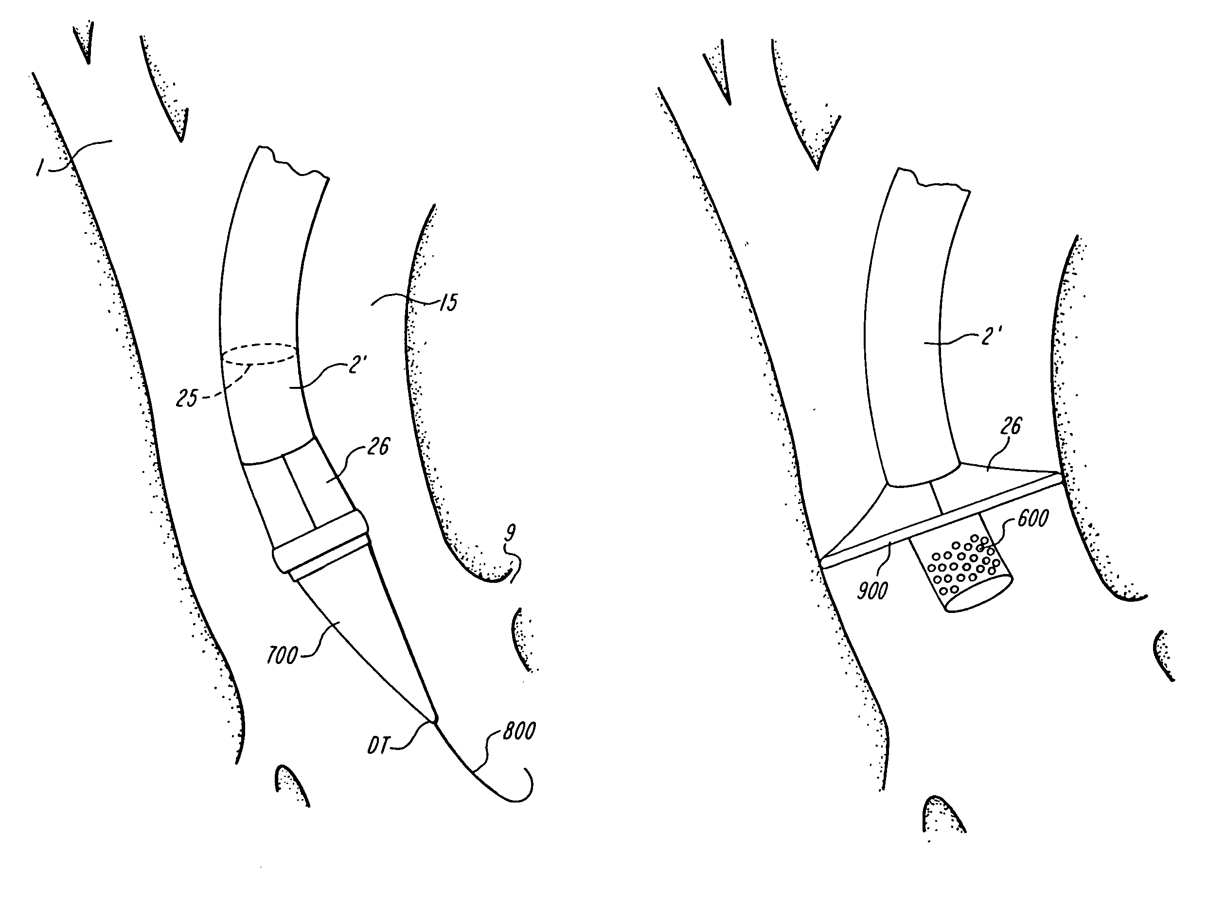
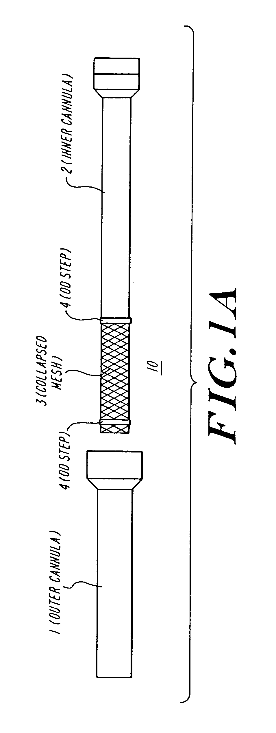
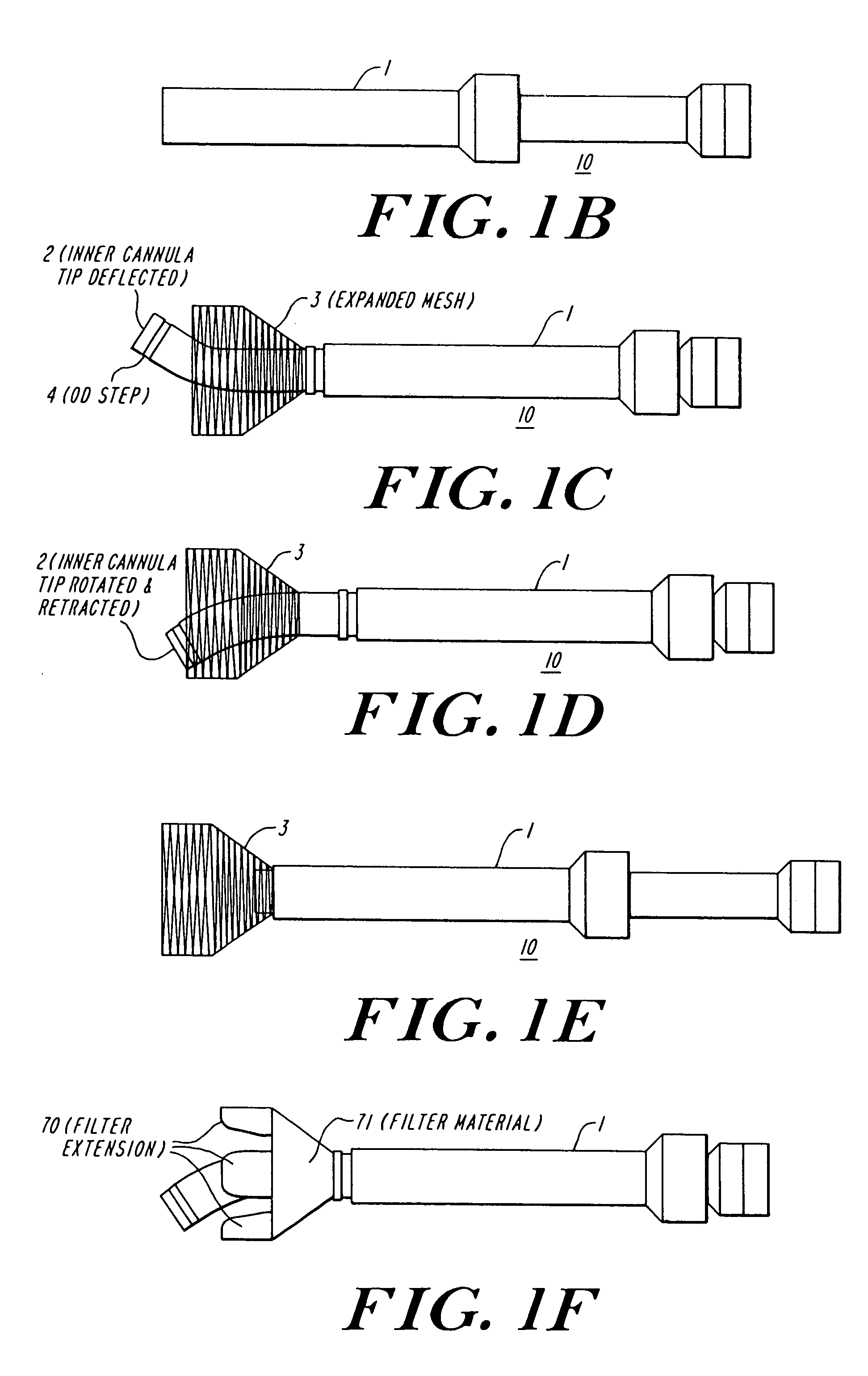
[0055]FIGS. 1A–1F depict multiple stages of deployment of an exemplary temporary filter device 10 of the present invention. This device is particularly useful during the manipulation and / or resection of a cardiac valve.

[0056]FIG. 1A shows the three primary components of the filter d...


PUM


Abstract

The present invention discloses devices and methods for performing intravascular procedures with out cardiac bypass. The devices include various embodiments of temporary filter devices, temporary valves, and prosthetic valves.The temporary filter devices have one or more cannulae which provide access for surgical tools for effecting repair of the cardiac valves. A cannula may have filters of various configurations encircling the distal region of the cannula, which prevent embolitic material from entering the coronary arteries and aorta.The temporary valve devices may also have one or more cannulae which guide the insertion of the valve into the aorta. The valve devices expand in the aorta to occupy the entire flow path of the vessel. In one embodiment, the temporary valve is a disc of flexible, porous, material that acts to filter blood passing therethrough. A set of valve leaflets extend peripherally from the disc. These leaflets can alternately collapse to prevent blood flow through the valve and extend to permit flow.The prosthetic valves include valve fixation devices which secure the prosthetic valve to the wall of the vessel. In one embodiment, the prosthetic valves have at least one substantially rigid strut, at least two expandable fixation rings located about the circumference of the base of the apex of the valve, and one or more commissures and leaflets. The prosthetic valves are introduced into the vascular system a compressed state, advanced to the site of implantation, expanded and secured to the vessel wall.

Description

BACKGROUND[0001]Of all valvular heart lesions, aortic stenosis carries the worst prognosis. Within one year of diagnosis, half of patients with critical aortic stenosis have died, and by three years this figure rises to 80%. Currently, there is only one effective treatment for patients with aortic stenosis—aortic valve replacement via open heart surgery. Unfortunately, this is a substantial and invasive undertaking for the patient.[0002]While there have been significant advances in heart valve technology over the last thirty years, there has been little progress in the development of safer and less invasive valve delivery systems. Aortic valve replacement currently requires a sternotomy or thoracotomy, use of cardiopulmonary bypass to arrest the heart and lungs, and a large incision on the aorta. The native valve is resected through this incision and a prosthetic valve is sutured to the inner surface of the aorta with a multitude of sutures passing into the wall of the aorta. This p...

Claims


Application Information

Patent Timeline
Patent Type & Authority Patents(United States)
IPC IPC(8): A61F2/06A61F2/24A61M5/00
CPCA61F2/2427A61F2/2418A61F2/2412A61F2220/0016A61F2250/0059
Inventor LAMBRECHT, GREGORY H.LIDDICOAT, JOHNMOORE, ROBERT KEVIN
Owner MEDTRONIC INC
Why Eureka
Try Eureka