
Tidal vertical flow wastewater treatment system and method

a wastewater treatment system and vertical flow technology, applied in water cleaning, separation processes, filtration separation, etc., can solve the problems of poor denitrification performance of the tidal flow system, the inability to reliably meet tertiary treatment standards for bod/sub>5/sub>and tss effluent values of sshf wetland, and the notorious poor nitrification in sshf wetlands, etc., to improve the performance of substantially anaer

Inactive Publication Date: 2005-05-24
DHARMA IP
View PDF69 Cites 33 Cited by
  • Summary
  • Abstract
  • Description
  • Claims
  • Application Information

AI Technical Summary

Benefits of technology

[0020]Another aspect of the system is for improving a performance of a subsurface horizontal flow wetland wastewater treatment device. This system may be used, for example, to retrofit onto an existing SSHF wetland, and comprises a vertical flow marsh cell as above, and means for transporting water exiting the marsh cell outlet to a top surface of the wetland adjacent a first end thereof. Means are also provided for recycling water from a wasteland outlet adjacent a second end.
[0023]A second embodiment of a method of the present invention is for improving a performance of a substantially anaerobic / anoxic subsurface horizontal flow wetland wastewater treatment device. This aspect comprises the step of transporting water from the wetland to a second environment that contains a negatively charged surface to which ammonia ions can adsorb. The adsorbed ammonia ions are then aerated by exposure thereof to atmospheric oxygen when the second environment is drained, thereby permitting nitrification of the ammonia ions into nitrate ions. Next the second environment is flooded to permit the nitrate ions to desorb into bulk water, which is then transported back to the wetland, where the nitrate ions are exposed to bacterial respiration to yield nitrogen gas.
[0024]A third embodiment of a method of the present invention serves to improve consumption of human pathogens by incorporating a lagoon between the discharge of the wetland and final discharge of system effluent. Zooplankton within the lagoon consume biological particles of the size classes that comprise human pathogens. The lagoon may also serve to equalize recycle flow and store irrigation water.

Problems solved by technology

Previously known tidal flow systems are believed to have poor denitrification performance, with the exception of a reciprocating tidal flow system as taught by Behrends (U.S. Pat. No. 5,863,433).
Despite this advantage, both BOD5 and TSS effluent values from SSHF wetland cannot reliably be expected to meet tertiary treatment standards.
Nitrification in SSHF wetlands is notoriously poor.
In practice this advantage is often not realized because of surfacing and ponding of wastewater resulting from clogging of wetland media.
Horizontal flow path velocities are insufficient to carry inorganic fines and recalcitrant organic materials through the media to the wetland outlet.
Although wastewater will eventually submerge again into the downstream media, some ponding is unavoidable in this situation.
Contact of wastewater with plant roots has previously been thought to play a significant role in treatment; however, there is growing evidence that this is not the case.
The treatment effect of roots is likely to be poorly distinguished from that of media if the media surface area is very large compared with that of plant roots.
A dead zone frequently results due to the deposition of organic material and the lack of circulation and re-aeration in this zone.
Obviously, the potential treatment role of roots cannot be determined if there is minimal root contact with wastewater.
Previously known tidal flow systems are believed to have poor denitrification performance, with the exception of a reciprocating tidal flow system as taught by Behrends (U.S. Pat. No. 5,863,433).

Method used


Image

  • Tidal vertical flow wastewater treatment system and method
  • Tidal vertical flow wastewater treatment system and method
  • Tidal vertical flow wastewater treatment system and method

Examples


Embodiment Construction

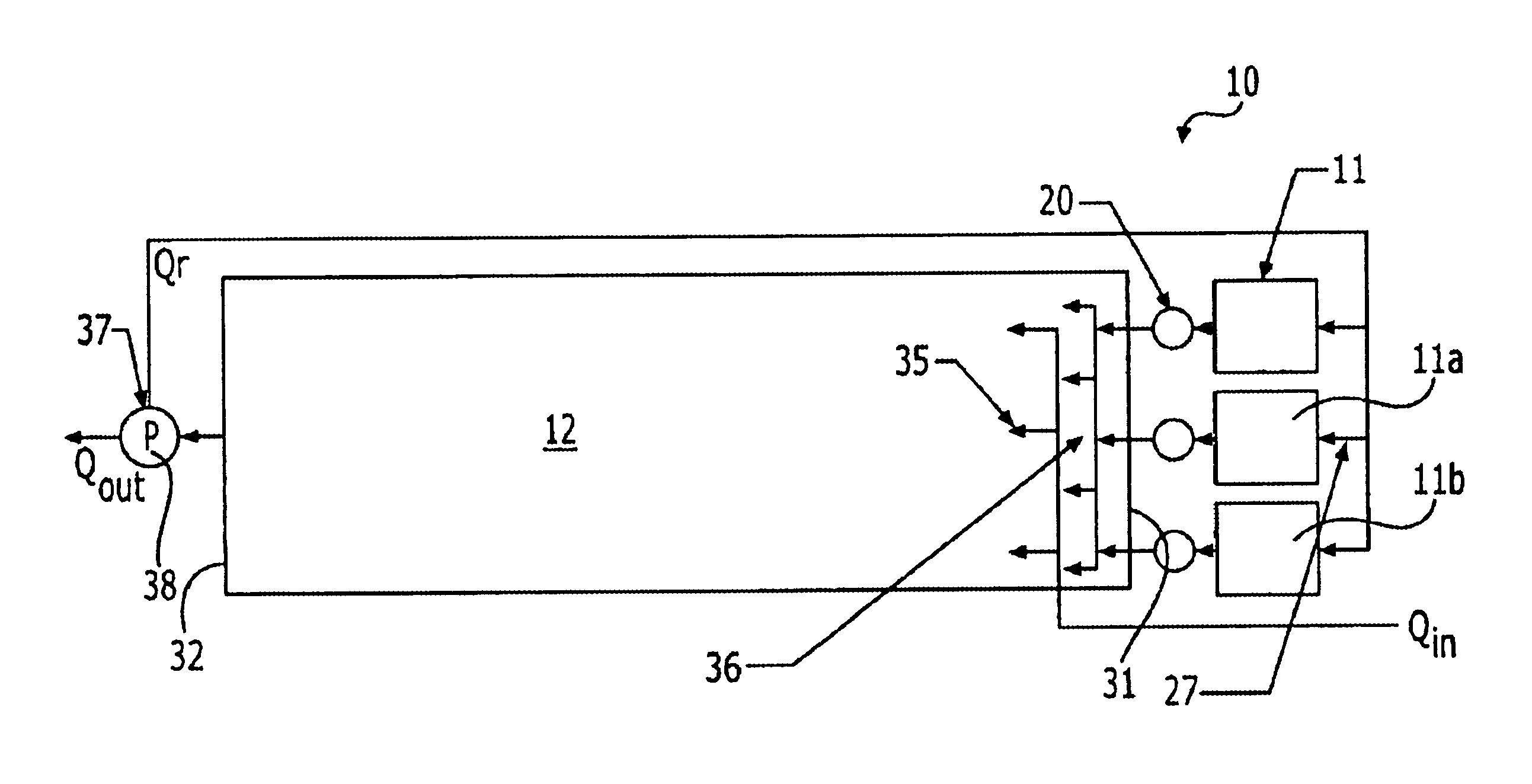
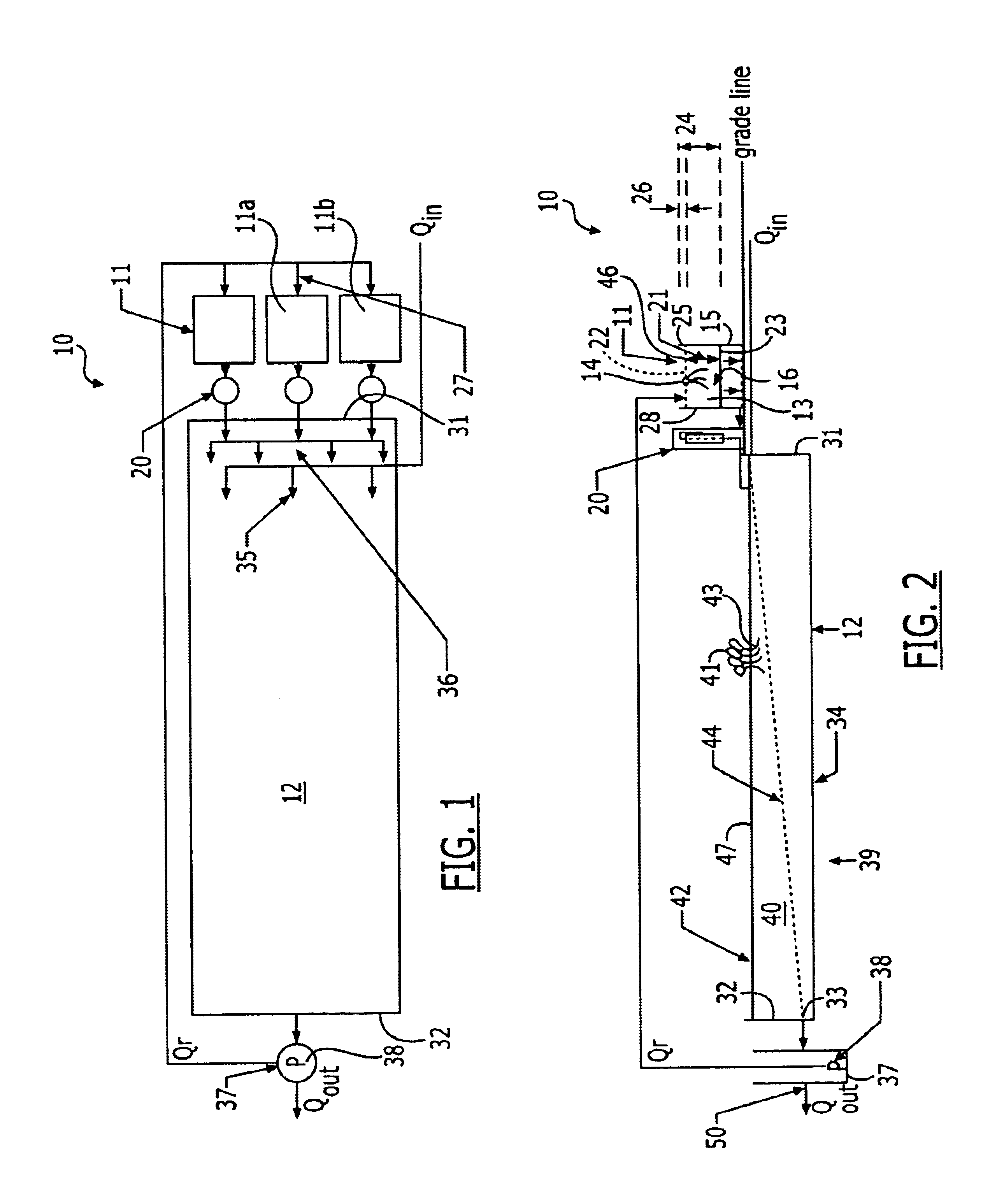
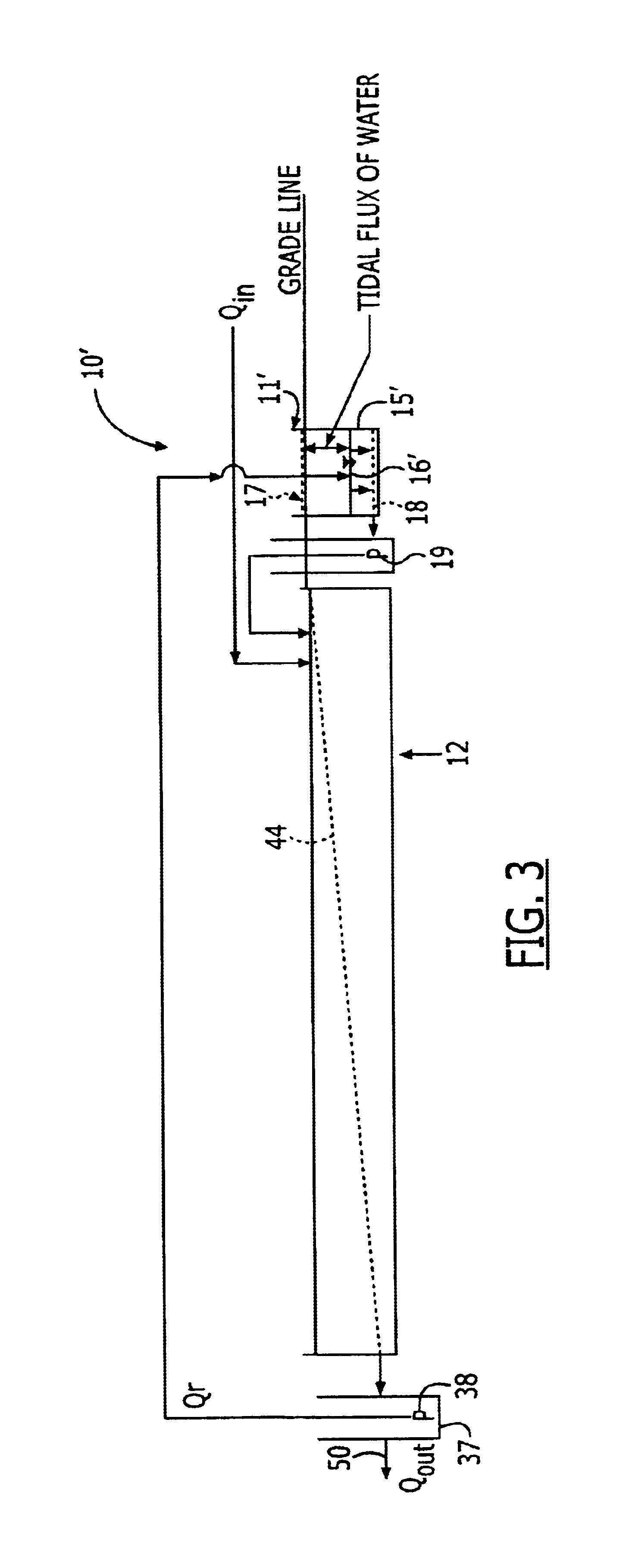
[0029]A description of the preferred embodiments of the present invention will now be presented with reference to FIGS. 1-3.

System Elements

[0030]A preferred embodiment of the present invention comprises a system 10 that includes a vertical flow marsh cell 11 in fluid communication with a subsurface horizontal flow wetland 12. The system 10 may be installed as depicted, or the marsh cell 11 and associated components may be added to an existing wetland 12 (“retrofit”) to improve the performance thereof. Preferably, depending upon the site characteristics, the system 10 may comprise a plurality of marsh cells 11 shown here as three marsh cells 11,11a,11b, configured in parallel, although this is not intended as a limitation. As these are substantially identical, only one marsh cell 11 will be described herein. In another embodiment (FIG. 3), a below-round system 10′ with a marsh cell 11′ is depicted.

[0031]In a preferred embodiment, the marsh cell 11 comprises a substantially impermeabl...


PUM

PropertyMeasurementUnit
depthaaaaaaaaaa
diameteraaaaaaaaaa
diameteraaaaaaaaaa

Abstract

A wastewater treatment system includes a vertical flow marsh cell that is adapted to contain media and to support plants having roots extending into the media, the roots and media positioned to contact water flowing downward through the marsh cell during a flooding stage, the media and plant roots providing surfaces to which biofilms can adsorb, the biofilms containing bacteria adapted to adsorb ammonium ions and nitrify ammonium ions to nitrate during an aerated drained phase. The marsh cell is configured to receive water from an outlet of a horizontal wetland that functions essentially anaerobically / anoxically to contain bacteria for transforming nitrate into nitrogen gas. Water to be treated and water exiting the marsh cell outlet are transportable to a wetland inlet, providing dilution of incoming wastewater. Treated water is discharged from the wetland outlet.

Description

BACKGROUND OF THE INVENTION[0001]1. Field of the Invention[0002]The present invention relates generally to wastewater treatment systems and methods, and, more particularly, to such systems and methods using bioremediation techniques.[0003]2. Related Art[0004]Engineered wetlands for wastewater treatment are known to have three basic hydraulic configurations: surface flow (SF), subsurface horizontal flow (SSHF), and vertical flow (VF). The first two are believed the most common, and are known to have significant design shortcomings. Even though an early wastewater treatment wetland design utilized vertical flow, design criteria are still considered experimental for vertical flow wetlands. Surface-loaded, vertical-flow wetlands are believed advantageous because surface loading forces flow through the root zone.[0005]The basic hydraulic flow path for VF wetlands is for wastewater to be introduced at the wetland surface, pass through media and plant roots, then to flow out of the wetland...

Claims


Application Information

Patent Timeline
Patent Type & Authority Patents(United States)
IPC IPC(8): C02F3/30C02F3/32
CPCC02F3/302C02F3/327C02F2103/001Y02W10/10
Inventor AUSTIN, DAVID C.
Owner DHARMA IP
Learn More