Method of laser milling using constant tool path algorithm

a constant tool path and laser milling technology, applied in the direction of manufacturing tools, electrical programme control, welding/soldering/cutting articles, etc., can solve the problems of low tolerance for error, waste of time and energy, and smaller tolerances for finished products in laser micromachining

Inactive Publication Date: 2005-05-24
PANASONIC CORP
View PDF7 Cites 62 Cited by
  • Summary
  • Abstract
  • Description
  • Claims
  • Application Information

AI Technical Summary

Benefits of technology

[0012]Further areas of applicability of the present invention will become apparent from the detailed description provided hereinafter. For example, while the present invention is described herein with reference to modifying angular speed as a function of radius for a spiral tool path that is round in shape, it should be understood that a constant arc speed can be obtained differently for different applications requiring a spiral that is not round in shape

Problems solved by technology

There exist multiple methods for laser machining; however, when fine features are to be drilled, tolerances are smaller for the finished product in laser micromachining.
This opportunity should not be squandered, as many problems continue to exist related to micromachining.
One problem that persists in the field relates to avoiding manufacturing off-specification products with micromachining.
This problem is persistent because, in micromachining, the tolerance for error is low and consistency is critical from product to product.
When a process is not consistent or repeatable, the manufacturing line produces off-specification products that result in wasted time and energy, mandatory rework, and reduced throughput.
This in turn reduces profitability of a manufacturing facility.
Another persistent problem related to micromachining involves production of consistent, repeatable results in milling.
However, current methods of milling are not designed to ensure that the required hole geometry is consistent from item to item in the manufacturing

Method used


Image

  • Method of laser milling using constant tool path algorithm
  • Method of laser milling using constant tool path algorithm
  • Method of laser milling using constant tool path algorithm

Examples


Embodiment Construction

[0021]The following description of the preferred embodiment(s) is merely exemplary in nature and is in no way intended to limit the invention, its application, or uses.

[0022]The present invention is a method of milling using a constant tool path algorithm (or alternatively, “milling algorithm”) that can be used to produce holes in a consistent, repeatable process. Further, the process can be used to parallel-process a plurality of milled holes simultaneously.

[0023]As noted above, an algorithmic approach proves mildly successful, in that a desired shape is produced using a constant angular velocity and tool pitch. As also noted above, this process does not compensate for the spacing of exposure steps generated near the center of the hole.

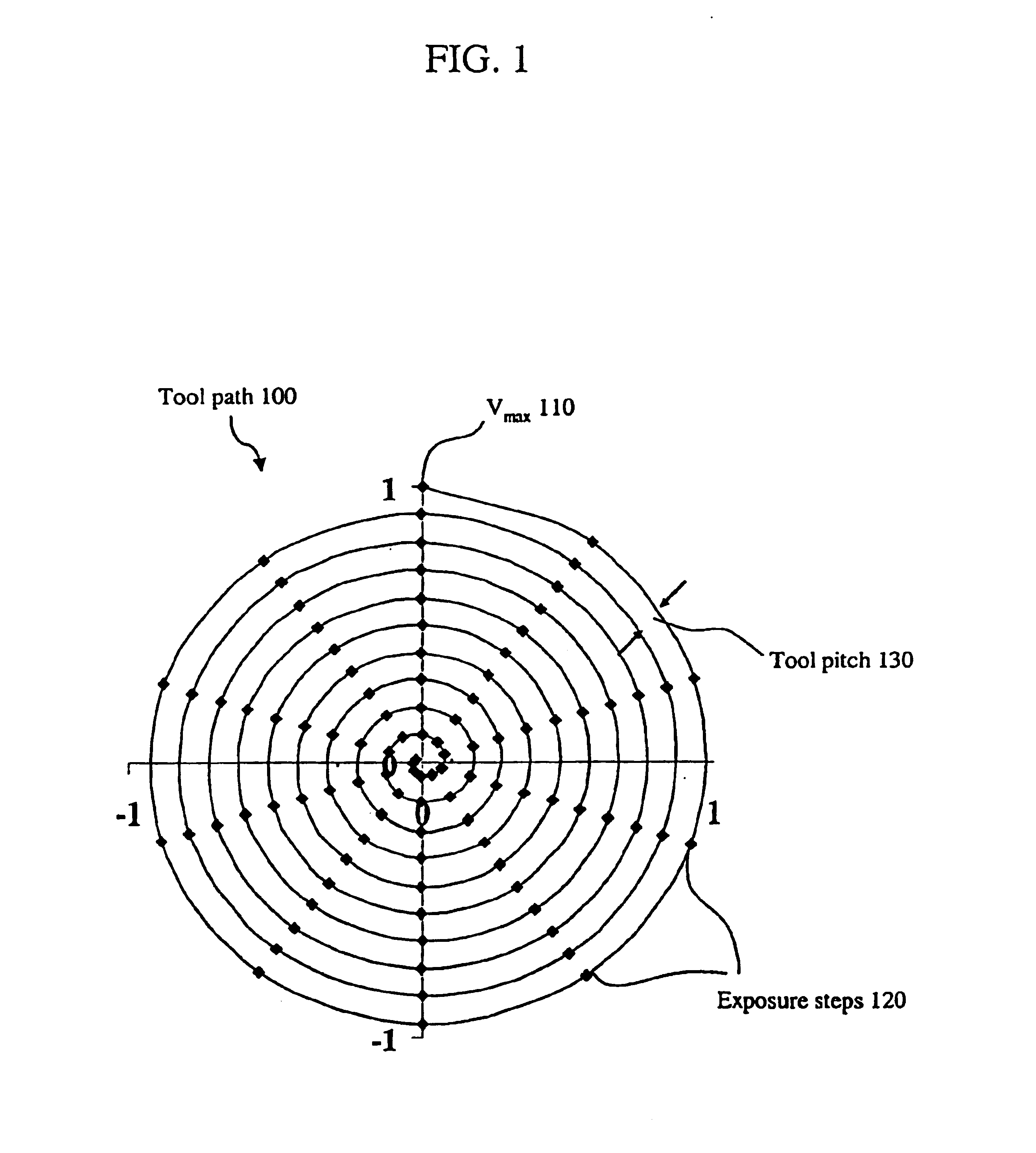
[0024]Referring to FIG. 1, a constant angular velocity tool path (tool path) 100 includes an initial voltage at the outer contour (Vmax) 110, a plurality of laser exposure steps 120, and the spacing of tool pitch 130. Using this approach, a large num...


PUM

PropertyMeasurementUnit
Fractionaaaaaaaaaa
Fractionaaaaaaaaaa
Fractionaaaaaaaaaa

Abstract

A method of creating a milled structure in a fixed material using a moving laser beam is disclosed, where a picosecond laser provides short pulses of light energy to produce required exposure steps, where a variable rate of laser beam movement conducts the milling upon the material, where the laser beam tool path directs the milling process to produce a milled hole of high quality and repeatability, and where the knowledge of how to measure these 3 quantities is returned as feedback into the laser system. The present invention is further embodied as a spiral milled tool path structured to achieve the customer specified tapered hole shape. The constant arc speed tool path is required to produce tapered holes to customer specification.

Description

CROSS-REFERENCE TO RELATED APPLICATIONS[0001]This application claims the benefit of U.S. Provisional Application No. 60 / 334,746, filed on Nov. 30, 2001. The disclosure of the above application is incorporated herein by reference.FIELD OF THE INVENTION[0002]The present invention generally relates to material ablation with pulsed light sources and particularly relates to laser drilling and laser milling.BACKGROUND OF THE INVENTION[0003]Material ablation by pulsed light sources has been studied since the invention of the laser. Reports in 1982 of polymers having been etched by ultraviolet (UV) excimer laser radiation stimulated widespread investigations of the process for micromachining. Since then, scientific and industrial research in this field has proliferated—mostly spurred by the remarkably small features that can be drilled, milled, and replicated through the use of lasers.[0004]Ultrafast lasers generate intense laser pulses with durations from roughly 10−11 seconds (10 picoseco...

Claims


Application Information

Patent Timeline
IPC IPC(8): B23K26/067B23K26/36B23K26/00B23K26/38B23K26/06B23K26/08B41J2/16H05K3/00B41J2/135B23K26/04B23K26/10G05B19/416
CPCB23K26/0608B23K26/4065B23K26/067B23K26/0676B23K26/08B23K26/0807B23K26/383B23K26/386B23K26/388B41J2/162B41J2/1634B23K26/4005B23K26/4025B23K26/0635H05K3/0026B23K26/04B23K26/10B23K26/364B23K26/082B23K26/382B23K26/0624B23K26/384B23K26/40B23K26/389B23K2103/172B23K2103/42B23K2103/50
Inventor CHENG, CHEN-HSIUNGLIU, XINBING
Owner PANASONIC CORP
Why Eureka
Try Eureka