
Method of manufacturing composite member, photosensitive composition, porous base material, insulating body and composite member

a composite member and composition technology, applied in the field of composite member manufacturing, can solve the problems of difficult to form a fine wiring pattern and a three-dimensional wiring pattern, serious problems remain unsolved in this technology, and achieve the effect of low cos

Inactive Publication Date: 2005-05-31
KK TOSHIBA
View PDF9 Cites 22 Cited by
  • Summary
  • Abstract
  • Description
  • Claims
  • Application Information

AI Technical Summary

Benefits of technology

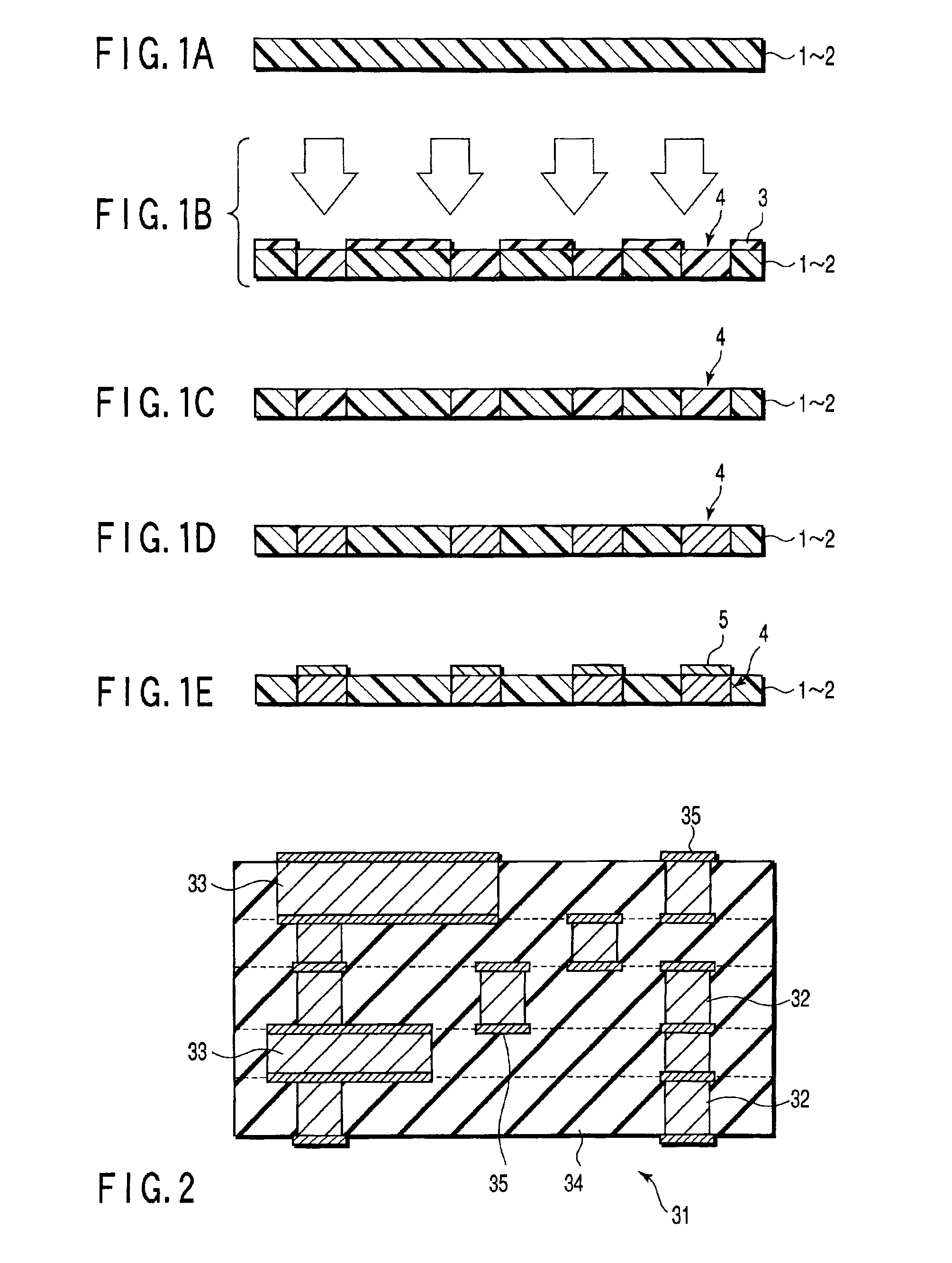
[0016]An object of the present invention is to provide a method of manufacturing a composite member having a conductive pattern formed on a base material of an insulating body, i.e., a method of manufacturing a composite member capable of forming a fine three-dimensional wiring pattern at low cost without causing the photosensitive layer to be dissolved in a plating solution so as to be peeled off.
[0019]Another object of the present invention is to provide a method of manufacturing a composite member allowing a high degree of freedom in the design of a conductive circuit, free from deterioration of the insulating body caused by light exposure, and free from an abnormal precipitation of a metal on the insulating body so as to make it possible to form easily a conductive portion having a fine pattern.

Problems solved by technology

However, this technology is troublesome.
In addition, it is difficult to form a fine wiring pattern and a three-dimensional wiring pattern by this technology.
However, a serious problem remains unsolved in this technology.
However, since the amount of the ion-exchange groups is small, the adsorption amount of the catalytic nuclei is not sufficiently large, resulting in failure to achieve satisfactory plating.
In conclusion, the conventional method is incapable of satisfying simultaneously both the improvement in the adsorption amount of the catalytic nuclei and the improvement in the resistance of the photosensitive layer to the plating solution.
However, this conventional method gives rise to the problem that, if the amount of the ion-exchange groups is increased in order to increase the adsorption amount of the catalytic nuclei, the photosensitive layer is dissolved in the plating solution.
Therefore, the via formation is laborious and it is difficult to improve the yield.
In the method utilizing formation of a via hole in an insulating body, however, it is difficult to form freely a fine via not larger than scores of microns in a desired position.
In the conventional method described above, however, light having a short wavelength is used for the light exposure, with the result that the material constituting the three-dimensional porous film is caused to deteriorate.
An additional problem to be noted is that the light used for the light exposure is absorbed by the three-dimensional porous film, resulting in failure to permeate deep inside the porous body.
Therefore, it is difficult to remove completely the metal salt adsorbed on the portion corresponding to the unexposed portion after the light exposure.
The abnormal precipitation of the metal nuclei gives rise to a problem in the insulating characteristics between the adjacent vias and between the adjacent wiring layers in accordance with miniaturization of the pattern.

Method used


Image

  • Method of manufacturing composite member, photosensitive composition, porous base material, insulating body and composite member
  • Method of manufacturing composite member, photosensitive composition, porous base material, insulating body and composite member
  • Method of manufacturing composite member, photosensitive composition, porous base material, insulating body and composite member

Examples


example i-1

[0269]In the first step, a photosensitive composition was dissolved in a mixed solvent consisting of 1% by weight of cyclohexanone and toluene so as to prepare a mixed solution. The photosensitive composition used for preparing the mixed solution contained a photosensitive compound of a polyfunctional peroxide ester, i.e., 3,3′,4,4′-tetra-(tert-butyl peroxy carbonyl)benzophenone (manufactured by Nippon Yushi K.K. under the trade name of BTTB), a crosslinkable polymer capable of a radical reaction, i.e., copolymer between polyvinyl ethylene PVE and polymethyl methacrylate PMMA (PVE:PMMA=1:3), and a coloring matter sensitive to a visible light of 3,3′-carbonyl bis(7-diethylamino cumarin) (manufactured by Hayashihara Biochemical Research Laboratory under the trade name of NKX-653). The weight ratio of the photosensitive compound, the crosslinkable polymer and the coloring matter contained in the photosensitive composition was 10:10:1.

[0270]On the other hand, prepared was a PTFE porous ...

example i-2

[0277]Prepared as an insulating body was a unwoven fabric made of glass fibers each having a diameter of 5 μm, having pores each having a diameter of 1 μm to 10 μm formed therein, and having a thickness of 50 μm.

[0278]Prepared was a composite member having a pattern of vias each having a diameter of 200 μm by using a photosensitive composition equal to that used in Example I-1 described above and by the procedure similar to that of Example I-1. Also prepared were wiring sheets and via sheets by using PTFE porous sheets each having an average pore diameter of 0.5 μm and a thickness of 20 μm by the procedure equal to that described previously.

[0279]Further, a multi-layered wiring board was prepared by using the resultant wiring sheets and via sheets. In the first step, a laminate structure was prepared by wrapping two wiring sheets each having an average pore diameter of 0.5 μm in a single via sheet, and the laminate structure thus prepared was arranged on both surfaces of the glass f...

example i-3

[0281]Prepared as an insulating body was an unwoven fabric made of PPS fibers each having a diameter of about 1 to 2 μm, which were prepared by a melt-blow method.

[0282]A composite member having a pattern of vias each having a diameter of 200 μm was prepared by using a photosensitive composition equal to that used in Example I-1 described previously and by the procedure equal to that employed in Example I-1.


PUM


Abstract

Disclosed is a method of manufacturing a composite member having a conductive pattern, comprising (1) forming on a surface of an insulating body a photosensitive layer containing both a photosensitive compound forming an ion-exchange group upon irradiation with an energy beam and a crosslinkable compound having a crosslinkable group, (2) forming a pattern of ion-exchange groups by selectively exposing the photosensitive layer to an energy beam so as to form an ion-exchange group in the exposed portion, (3) crosslinking the crosslinkable compound contained in at least the exposed portion of the photosensitive layer, (4) allowing metal ions, or a metal colloid to be adsorbed on the pattern of ion-exchange groups formed by the selectively exposing, and (5) forming a composite member having conductive pattern by depositing a conductive material on the pattern of ion-exchange groups having the metal ions, or the metal colloid adsorbed thereon using an electroless plating.

Description

CROSS-REFERENCE TO RELATED APPLICATIONS[0001]This application is based upon and claims the benefit of priority from the prior Japanese Patent Applications No. 2001-092715, filed Mar. 28, 2001; and No. 2001-093668, filed Mar. 28, 2001, the entire contents of both of which are incorporated herein by reference.BACKGROUND OF THE INVENTION[0002]1. Field of the Invention[0003]The present invention relates to a method of manufacturing a composite member, particularly, to a method of manufacturing a composite member having a flexible substrate, a multi-layered wiring board, an interposer, a fine wiring pattern such as three-dimensional wiring, an antenna, a coil, a sensor and a fine wiring pattern such as a micromachine. The present invention also relates to a photosensitive composition and a porous base material suitable for use in the manufacturing method of the composite member of the present invention.[0004]2. Description of the Related Art[0005]The present invention also relates to a m...

Claims


Application Information

Patent Timeline
IPC IPC(8): G03F7/38H05K3/18G03F7/027G03F7/075
CPCH05K3/185G03F7/38G03F7/027G03F7/0755
Inventor HIRAOKA, TOSHIROASAKAWA, KOJIHOTTA, YASUYUKIMATAKE, SHIGERU
Owner KK TOSHIBA
Learn More