Semiconductor integrated circuit device including first, second and third gates

a technology of integrated circuits and semiconductors, applied in semiconductor devices, digital storage, instruments, etc., can solve the problems of increasing the word line voltage, reducing the operation speed, and affecting the operation speed, so as to achieve high operation speed and low defect density

Inactive Publication Date: 2005-05-31
RENESAS ELECTRONICS CORP
View PDF30 Cites 26 Cited by
  • Summary
  • Abstract
  • Description
  • Claims
  • Application Information

AI Technical Summary

Benefits of technology

[0016]It is therefore an object of the present invention to provide a semiconductor integrated circuit device suitable f

Problems solved by technology

However, the inventors of the present invention have found that several problems develop when a higher integration density is sought in the memory cells described above.
However, when the word line width is decreased, the resistance value of the word line increases with the result that the rise of the word line voltage is

Method used


Image

  • Semiconductor integrated circuit device including first, second and third gates
  • Semiconductor integrated circuit device including first, second and third gates
  • Semiconductor integrated circuit device including first, second and third gates

Examples


embodiment 1

[Embodiment 1]

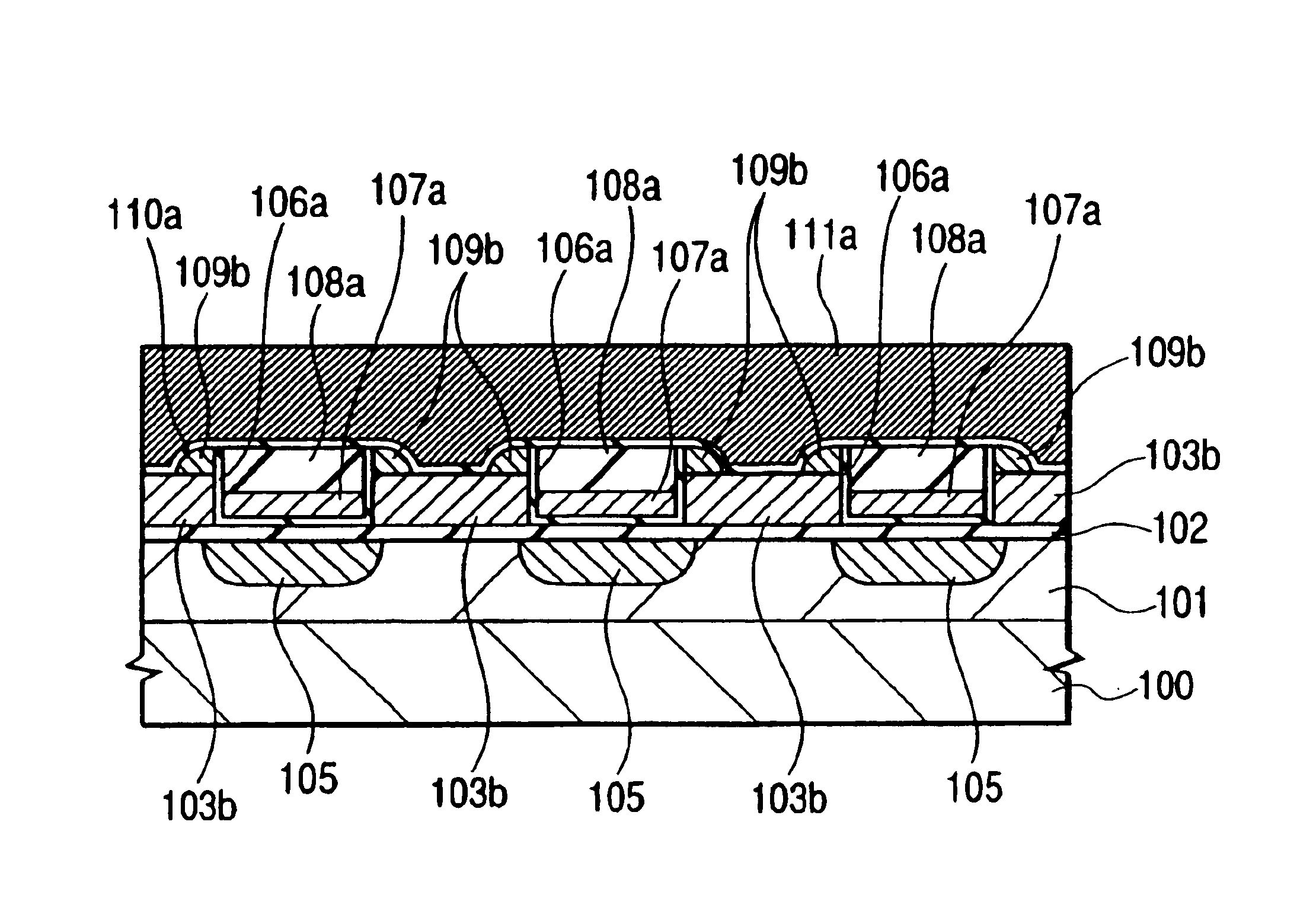
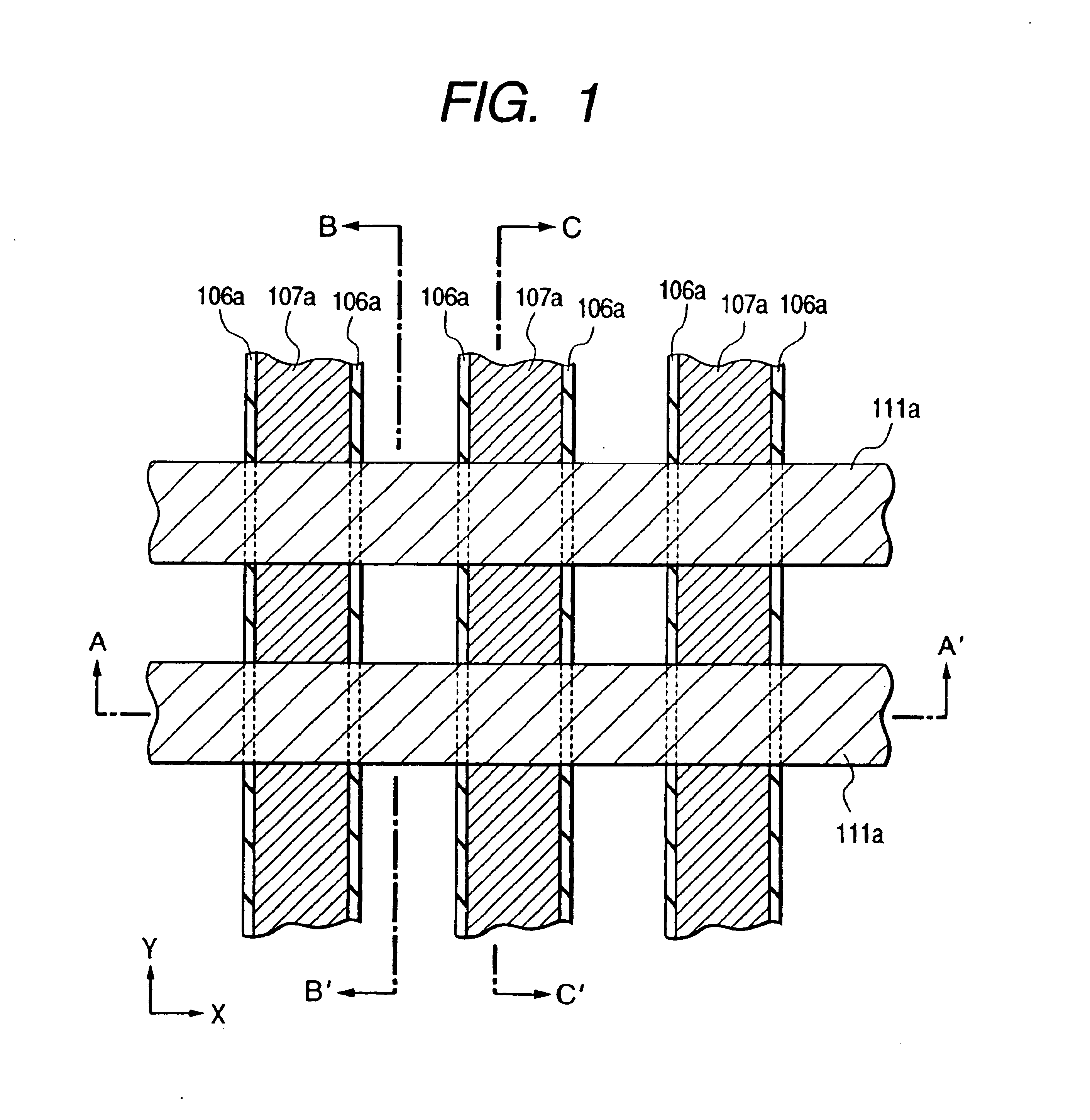
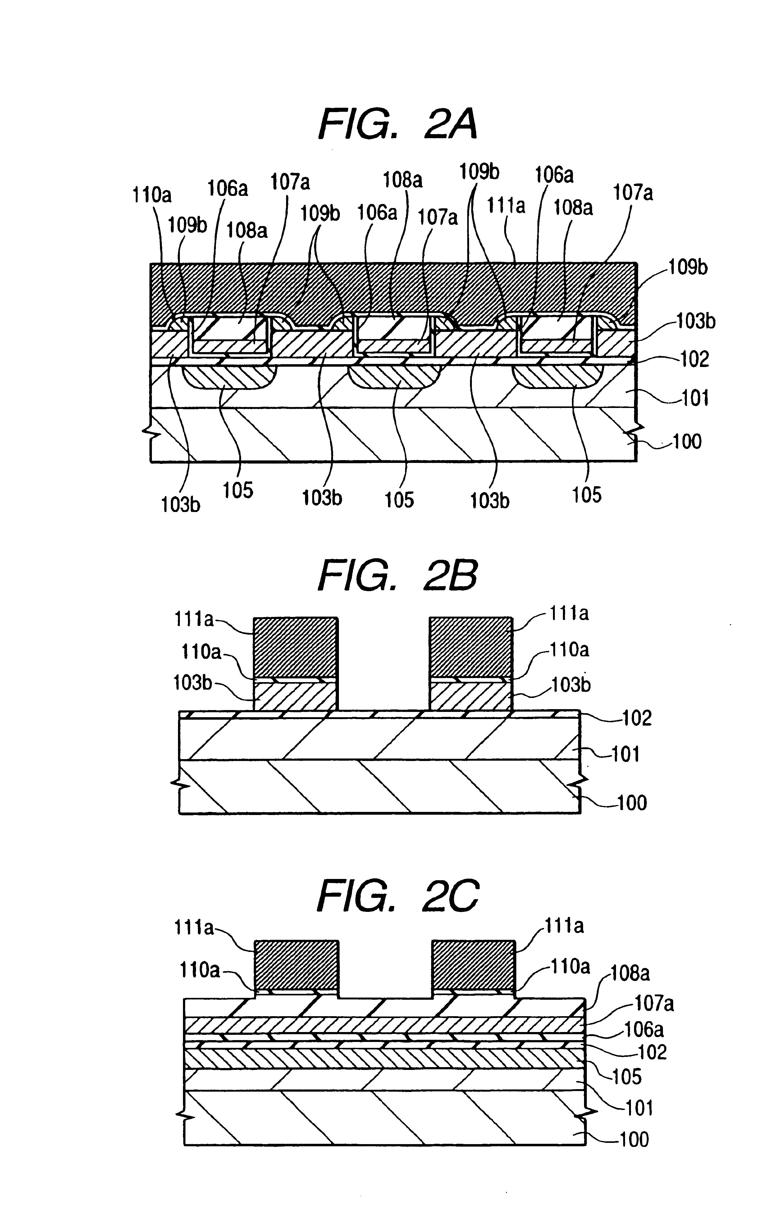
[0092]FIG. 1 is a partial plan view showing an example of the semiconductor integrated circuit device according to Embodiment 1 of the present invention. FIGS. 2A, 2B and 2C are sectional views taken along lines A-A′, B-B′ and C-C′ in FIG. 1, respectively. In the plan view of FIG. 1, hatching is applied to each member for ease of illustration and a part of members is omitted.

[0093]The semiconductor integrated circuit device of this embodiment has a memory cell of a so-called “flash memory”. The memory cell includes a source / drain 105 inside a well 101 formed on the main surface of a semiconductor substrate 100, a first gate (floating gate) 103b, a second gate (control gate) 111a and a third gate 107a. The control gate (second gate) 111a of each memory cell is connected to other in a row direction (x direction) and forms a word line WL.

[0094]The floating gate (first gate) 103b and the well 101 are isolated from each other by a gate insulator film (first insulator film) ...

embodiment 2

[Embodiment 2]

[0145]FIG. 16 is a sectional view showing an example of a semiconductor integrated circuit device according to Embodiment 2 of the present invention. The plan view of the semiconductor integrated circuit device of this embodiment is the same as FIG. 1 of the first embodiment. FIGS. 16A, 16B and 16C are sectional views taken along lines A-A′, B-B′ and C-C′ in FIG. 1, respectively.

[0146]The semiconductor integrated circuit device according to this embodiment is different from the semiconductor integrated circuit device of Embodiment 1 in only its source / drain diffusion layer 205. The materials of other members, their structures and arrangement, etc, are the same as those of Embodiment 1. Therefore, the explanation will be given on only the different portion, and the explanation of other members will be omitted.

[0147]The source / drain diffusion layer 205 is disposed vertically to the word line 111a and exists as a local source line and a local data line for connecting the ...

embodiment 3

[Embodiment 3]

[0174]FIG. 22 is a partial plan view showing an example of the semiconductor integrated circuit device according to Embodiment 3 of the present invention, and FIGS. 23A, 23B and 23C are sectional views taken along lines A-A′, B-B′ and C-C′ in FIG. 22, respectively. Incidentally, each member is shown hatched with some members being omitted for ease of illustration in the plan view of FIG. 22. FIGS. 23A, 23B and 23C are sectional views taken along lines A-A′, B-B′ and C-C′ in FIG. 22, respectively.

[0175]The construction of the semiconductor integrated circuit device of this embodiment is substantially the same as that of Embodiment 2 with the exception that the film thickness of the insulator film 606a between the floating gate 103b and the third gate 107a is increased. The materials, constructions, arrangements, etc, of other members are substantially the same as those of Embodiment 2. Therefore, the explanation will be given on only the different portions and will be o...


PUM


Abstract

In a semiconductor integrated circuit device including a third gate, the present invention improves miniaturization and operation speed and reduces a defect density of an insulator film. In a semiconductor integrated circuit device including a well of a first conductivity type formed in a semiconductor substrate, a source/drain diffusion layer of a second conductivity type inside the well, a floating gate formed over the semiconductor substrate through an insulator film, a control gate formed and isolated from the floating gate through an insulator film, word lines formed by connecting the control gates and a third gate formed and isolated from the semiconductor substrate, the floating gate and the control gate through an insulator film and different from the floating gate and the control gate, the third gate is buried into a space of the floating gates existing in a direction vertical to the word line and a channel.

Description

CROSS REFERENCE TO RELATED APPLICATIONS[0001]This is a Divisional application of Ser. No. 10 / 206,982, filed July 30, 2002, now U.S. Pat. No. 6,687,156, which is a Divisional application of Ser. No. 09 / 616,072, filed July 13, 2002, now U.S. Pat. No. 6,438,028, the entire disclosure of which is hereby incorporated by reference.BACKGROUND OF THE INVENTION[0002]This invention relates to a semiconductor integrated circuit device, and a production and operation method thereof. More particularly, this invention relates to a technology that will accomplish high integration density, high reliability and low operating voltage of an electrically programmable / erasable non-volatile semiconductor memory device.[0003]Among electrically programmable / erasable nonvolatile semiconductor memory devices, a so-called “flash memory” is known as a memory device capable of collectively erasing data. The flash memory has excellent portability and impact resistance, and can electrically and collectively erase...

Claims


Application Information

Patent Timeline
IPC IPC(8): G11C16/04H01L27/115H01L21/70H01L21/8247G11C11/34G11C16/12H01L29/423
CPCG11C16/0416G11C16/0425G11C16/12H01L29/42328H01L27/11521H01L27/11524H01L27/115H10B41/35H10B69/00H10B41/30
Inventor KOBAYASHI, TAKASHIKURATA, HIDEAKIKOBAYASHI, NAOKIKUME, HITOSHIKIMURA, KATSUTAKASAEKI, SHUNICHI
Owner RENESAS ELECTRONICS CORP
Why Eureka
Try Eureka