Film-sealed non-aqueous electrolyte battery with improved surface-treated lead terminal

Active Publication Date: 2005-06-07
NEC ENERGY DEVICES LTD +2
View PDF12 Cites 25 Cited by
  • Summary
  • Abstract
  • Description
  • Claims
  • Application Information

AI Technical Summary

Benefits of technology

[0019]It is a further object of the present invention to provide a novel surface-treated lead terminal for a film-sealed non-aqueous electrolyte battery providing a high adhesion reliability between the lead terminals and a sealant layer.
[0020]It is a still further object of the present invention to provide a novel surface-treated lead terminal for a film-sealed non-aqueous electrolyte battery preventing any corrosion of the lead terminal by a fluorine acid.
[0021]It is yet a further object of the present invention to provide a novel surface-treated lead terminal for a film-sealed non-aqueous electrolyte battery preventing any generation of contact resistance between the lead terminal

Problems solved by technology

If the sealing is imperfect to allow an entry of moisture from the outside of the battery case, then the electrolyte is deteriorated by the moisture, whereby the battery performance is deteriorated.
In this case, an adhered area between the metal plate-shaped lead terminals and a sealant layer of the laminated film case is likely to be deteriorated in sealing reliability to cause a peel between them and form a leak path.
First, it is generally difficult to obtain a strong adhesion between the metal surface and the polymer resin surface.
Se

Method used


Image

  • Film-sealed non-aqueous electrolyte battery with improved surface-treated lead terminal
  • Film-sealed non-aqueous electrolyte battery with improved surface-treated lead terminal
  • Film-sealed non-aqueous electrolyte battery with improved surface-treated lead terminal

Examples


embodiment

Preferred Embodiment

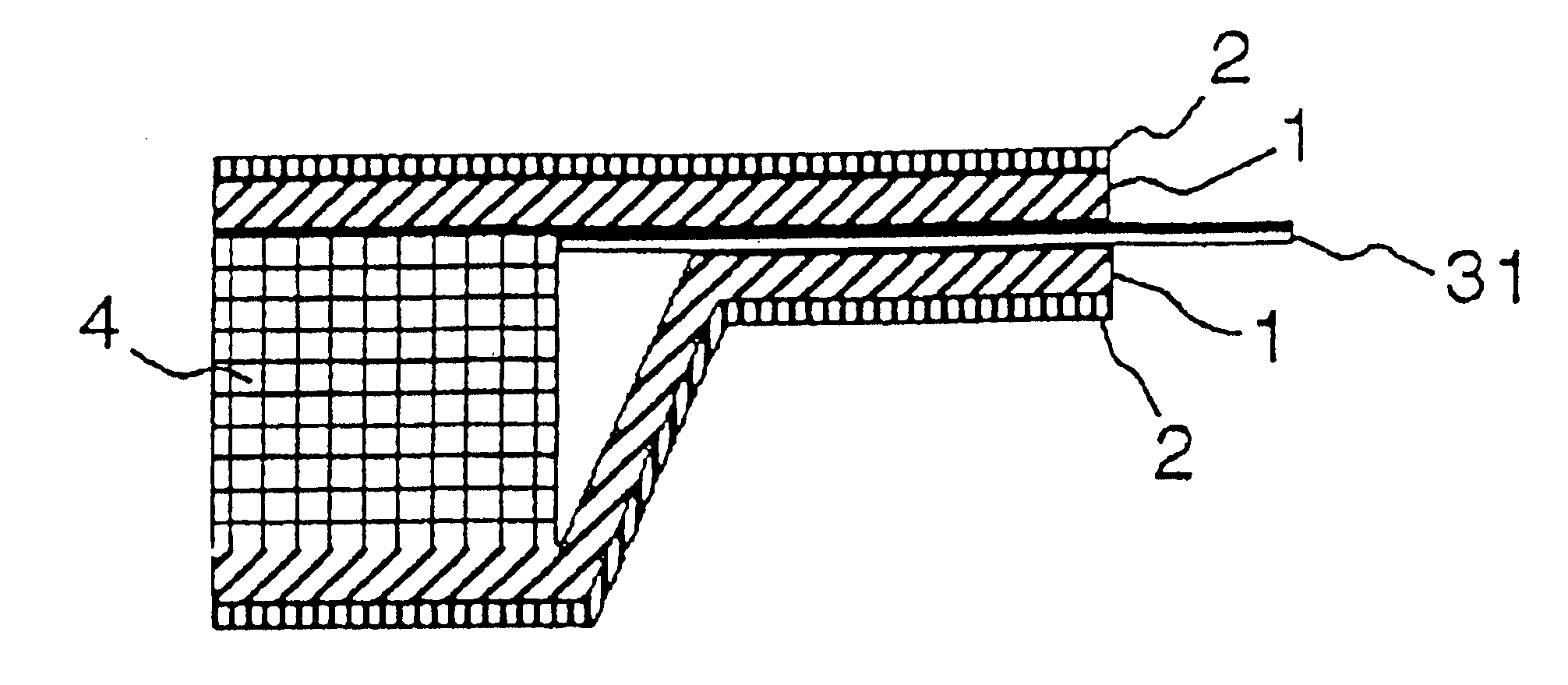
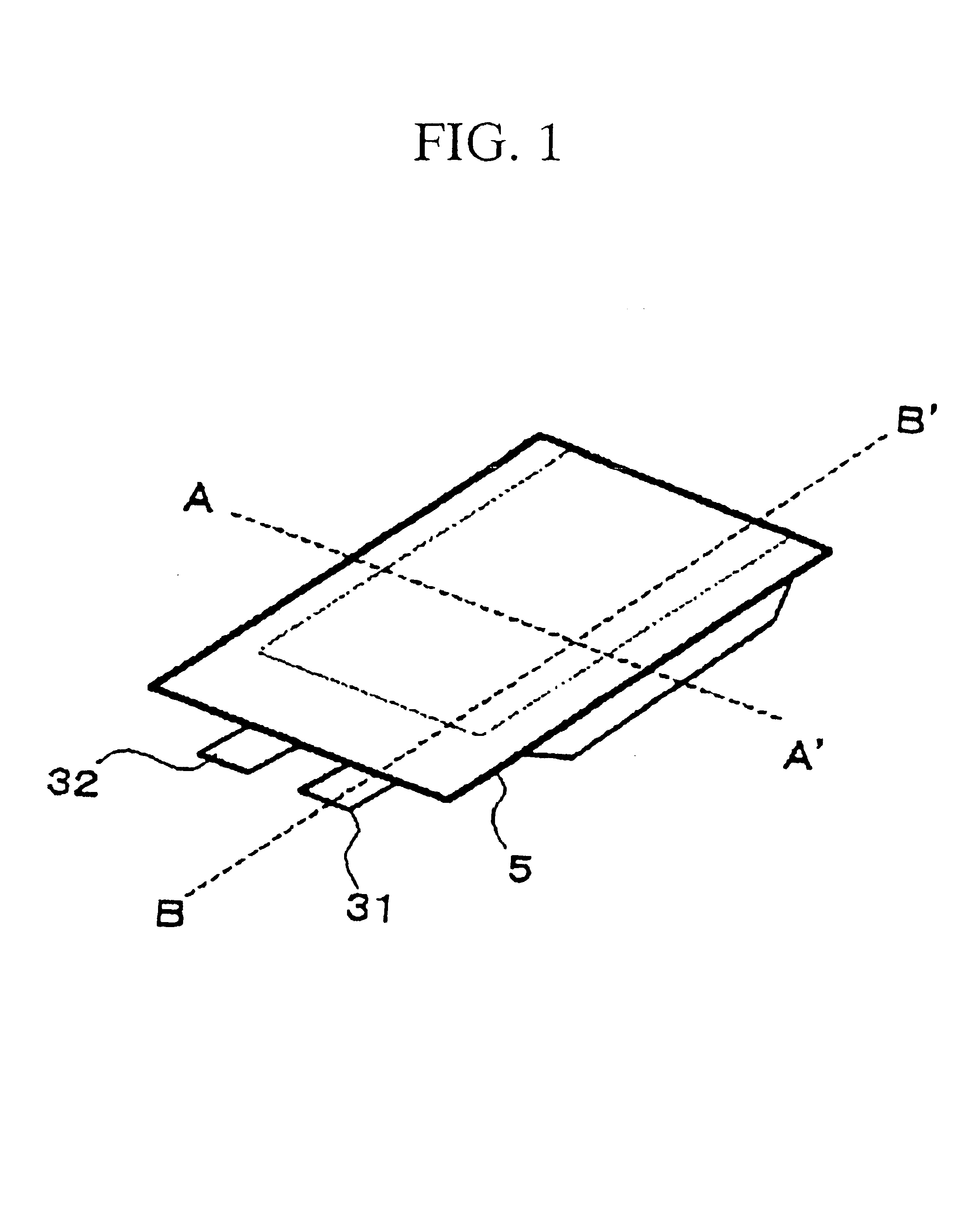
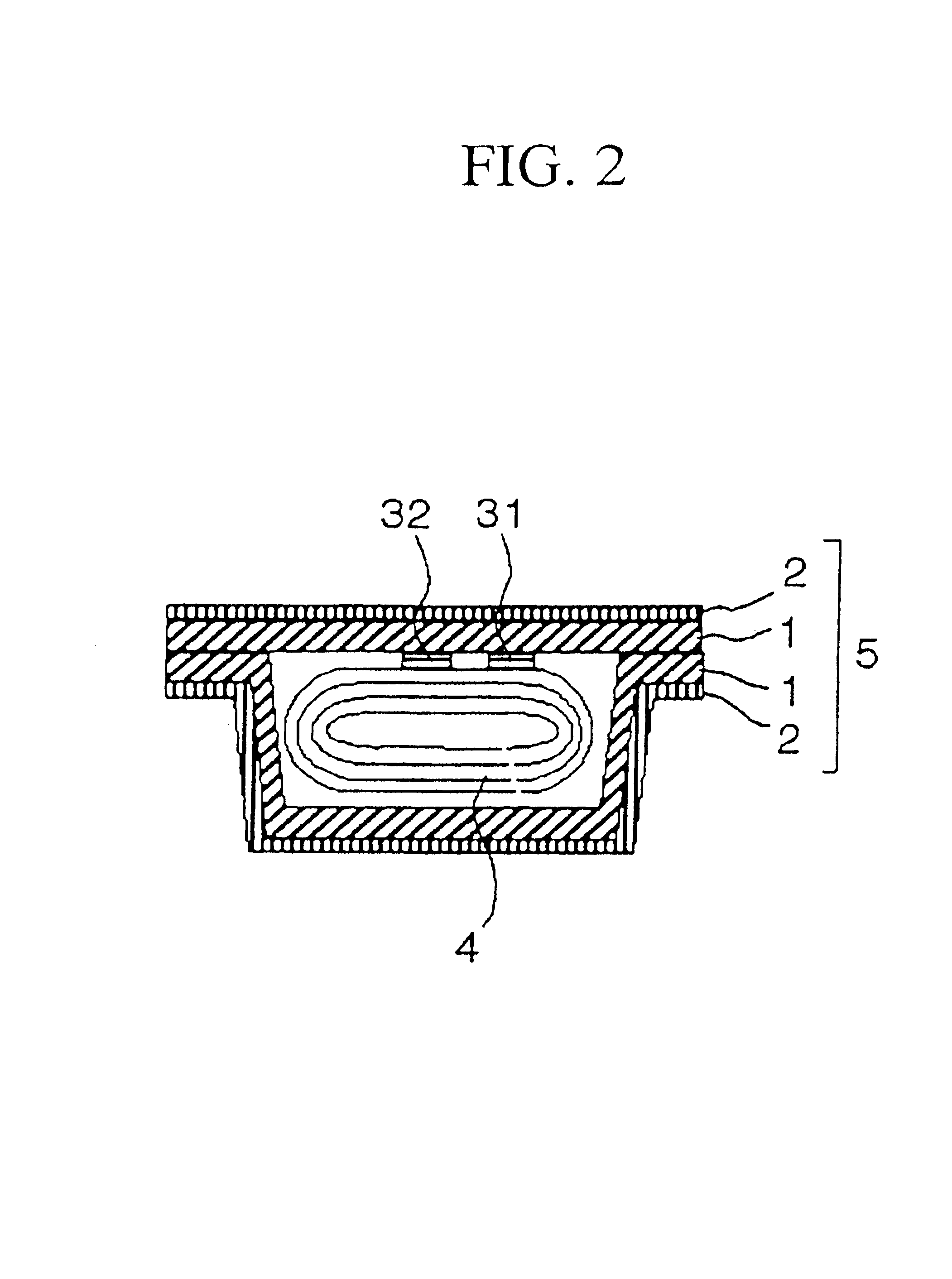
[0053]A preferred embodiment according to the present invention will be described in detail with reference to the drawings. FIG. 1 is a schematic perspective view of a film-sealed non-aqueous electrolyte battery in a preferred embodiment in accordance with the present invention. FIG. 2 is a cross sectional elevation view illustrative of the film-sealed non-aqueous electrolyte battery, taken along an A-A′ line of FIG. 1. FIG. 3 is an enlarged fragmentary cross sectional elevation view of the film-sealed non-aqueous electrolyte battery, taken along a B-B′ line of FIG. 1.

[0054]The film-sealed non-aqueous electrolyte battery mainly comprises a battery element 4 and a film case 5 which seals the battery element 4. The battery element 4 includes a non-aqueous electrolyte, a positive electrode, a negative electrode and a separator. The film case 5 further comprises laminations of a sealant polymer resin film 1, a metal foil 2 and a thermally stable resin film. The seala...

example 1

[0083]Lithium manganate powders of spinel structure, carbon donor providing conductivity, and polyvinylidene fluoride were blended at weight ratios of 90:5:5 into N-methylpyrolidone (hereinafter refereed to as NMP) and stirred to form a slurry containing NMP. An amount of NMP was adjusted in consideration of viscosity of the slurry. The slurry was uniformly applied by a doctor blade onto a first surface of an aluminum foil of 20 micrometers in thickness which is a positive collector for subsequent dry process in vacuum pressure at 100° C. for 2 hours. The slurry was also uniformly applied onto a second surface of the aluminum foil for subsequent dry process in vacuum pressure. This sheet was then rolled and pressed to form a positive electrode active material layer. A theoretical capacity was 600 mAh.

[0084]Amorphous carbon powders, and polyvinylidene fluoride were blended at weight ratios of 91:9 into N-methylpyrolidone (hereinafter referred to as NMP) and stirred to form a slurry c...

example 2

[0090]Lithium manganate powders of spinel structure, carbon donor providing conductivity, and polyvinylidene fluoride were blended at weight ratios of 90:5:5 into N-methylpyrolidone (hereinafter referred to as NMP) and stirred to form a slurry containing NMP. An amount of NMP was adjusted in consideration of viscosity of the slurry. The slurry was uniformly applied by a doctor blade onto a first surface of an aluminum foil of 20 micrometers in thickness which is a positive collector for subsequent dry process in vacuum pressure at 100° C. for 2 hours. The slurry was also uniformly applied onto a second surface of the aluminum foil for subsequent dry process in vacuum pressure. This sheet was then rolled and pressed to form a positive electrode active material layer. A theoretical capacity was 600 mAh.

[0091]Amorphous carbon powders, and polyvinylidene fluoride were blended at weight ratios of 91:9 into N-methylpyrolidone (hereinafter referred to as NMP) and stirred to form a slurry c...


PUM

PropertyMeasurementUnit
Thicknessaaaaaaaaaa
Thicknessaaaaaaaaaa
Nanoscale particle sizeaaaaaaaaaa

Abstract

A film-sealed nonaqueous electrolyte battery comprises: a battery element including a non-aqueous electrolyte; a film case having at least a sealant polymer resin film for sealing the battery element; at least a lead terminal extending from the battery element and projecting from the film case, and the lead terminal with a surface having a contact area in contact directly with the sealant polymer resin film, and at least the contact area of the surface of the lead terminal is coated with an anti-corrosion coating film, wherein the anti-corrosion coating film includes: (A) a polymer of structural units of a phenolic compound, and at least a part of the structural units includes a substituent which comprises an amino group or a substituted amino group; (B) a phosphate compound; and (C) a titanium fluorine compound.

Description

BACKGROUND OF THE INVENTION[0001]1. Field of the Invention[0002]The present invention relates to a battery, and more particularly to a film-sealed non-aqueous electrolyte battery including a non-aqueous electrolytic solution.[0003]2. Description of the Related Art[0004]Requirements for size reductions of various electronic devices have been on the increase. The importance for size reduction of the battery for realizing the size reductions thereof has also been on the increase. It is effective that a battery element for generating a power is accommodated in a thin film outer case, such as a laminated film case.[0005]The laminated film case comprises laminations of metal foils or sealing polymer resin layers. The laminated film case may seal the battery element by a heat-application. A high reliability of sealing the sealing portions of the laminated film case is necessary for isolating the battery element from the atmosphere and also preventing leakage of the electrolyte of the batte...

Claims


Application Information

Patent Timeline
IPC IPC(8): C23C22/05C23C22/36H01R13/52H01M2/06H01M2/08H01M2/30H01M2/02H01M6/04H01M10/36H01M10/40H01M6/10H01M50/571H01M10/05H01M10/052H01M10/0566H01M10/0568H01M10/058H01M50/105H01M50/55H01M50/553H01M50/562H01M50/566
CPCC23C22/36H01M2/06H01R13/5216H01M2/08H01M2/0207H01M2/0287Y02E60/122H01M2/30H01M10/0525H01M2006/106Y02E60/10H01M50/124Y02P70/50H01M50/562H01M50/105H01M50/55H01M50/553H01M50/566
Inventor YAGETA, HIROSHIKAWAI, HIDEMASASHIRAKATA, MASATOTAKASHIMA, TETSUYAKOJIMA, IKUOOHYAMA, NORIHIDEIIZUKA, HIROYUKI
Owner NEC ENERGY DEVICES LTD
Why Eureka
Try Eureka