Device for control of a hydraulically actuatable shifting element

a technology of hydraulic actuation and shifting element, which is applied in the direction of mechanical actuation clutches, interengaging clutches, and pressure pre-control valves customarily used as actuators. it can solve the problems of reducing the utilizable control range of the actuator, and reducing the number of actuators and structural elements. , the effect of less limitation of transmitting capacity

Inactive Publication Date: 2005-06-14
ZF FRIEDRICHSHAFEN AG
View PDF11 Cites 8 Cited by
  • Summary
  • Abstract
  • Description
  • Claims
  • Application Information

AI Technical Summary

Benefits of technology

[0023]The configuration of the second clutch valve as an inverse proportional valve, that is, which as the pressure-adjuster control pressure increases delivers to the reset space a lower pressure, has the advantage that the inventive device can be implemented with a lower number of actuators and structural elements.
[0024]In an advantageous embodiment of the invention can be provided that a holding valve is also associated with the clutch space. Such a holding valve, which can be designed in a manner known per se, holds the clutch closed even during transmission of high torques whereby the use of a clutch valve with a steep characteristic line and a correspondingly poorer ratio of transmitted torque to a quantity of output signal the same as a less limitation of the transmitting capacity can be eliminated.

Problems solved by technology

In such a structure, the needed shifting pressure has to be increased by the power of the counterpressure or of the spring tension thus reducing the available control range of a pressure pre-control valve or control valve customarily used as actuator.
In the typical case of use of a clutch in a powershift transmission, this means that approximately 15% of the pressure power needed to ensure the transmitting capacity of the clutch is supported on a housing via a spring in the reset space and is not available for the transmitting capacity.
This reduction of the utilizable control range of the actuator is especially problematic in an area of low pressure in which a pressure regulator usually shows a very flat behavior and to ensure a certain pressure power has to be substantially more heavily supplied with current than is the case in areas of higher pressure.
Particularly problematic are shifts to gears with a higher power ratio, since, on one hand, very high torques appear in the shifting elements and, on the other, high requirements are placed on the shifting quality due to the low speed.
This results in a conflict of interest in the layout of the shifting elements, since a high transmitting capacity requires a large clutch piston which disadvantageously is very sensitive to interruptions and needs a strong recoil spring.
However, a strong recoil spring has the disadvantages of great spring tension tolerance, great hysteresis and strong setting property together with the disadvantages typical in the use of springs.
To the latter belongs a larger installation space, as a rule, the requirement that the aging of the spring be taken into account in the new layout and high expenses for adaptations in the transmission software which take into account the tolerance of the spring in the new state and its wear characteristics.
In addition, a strong recoil spring has to be compensated by an adequate layout of the control valve which results in an impaired ratio of the transmitted torque in correlation to the expenditure amount and thus to an impairment of the degree of effectiveness.
Problematic here, on one hand, is the comparatively strong excitation pulse required to overcome the reaction inertia of the clutch piston and the fact that quantity of the output signal of the current of the control valve can be delivered only in discrete steps which, in as data amount imaginably to be processed, can result in a jerky movement of the clutch piston.
To implement a high transmitting capacity also requires a large friction surface to be distributed among a large number of friction elements or discs subject to a limited admissible contact pressure.
But a large number of friction elements disadvantageously implies a great air play and thus a long travel stroke.
In the solutions known from the practice where the clutch is shifting or the clutch piston adjusted against a cropping out counterpressure, there is, likewise, the disadvantage of the reduction of the control range available and of the impairment of the ratio of the control pressure to be applied relative to the transmissible torque of the clutch.

Method used


Image

  • Device for control of a hydraulically actuatable shifting element
  • Device for control of a hydraulically actuatable shifting element
  • Device for control of a hydraulically actuatable shifting element

Examples


Embodiment Construction

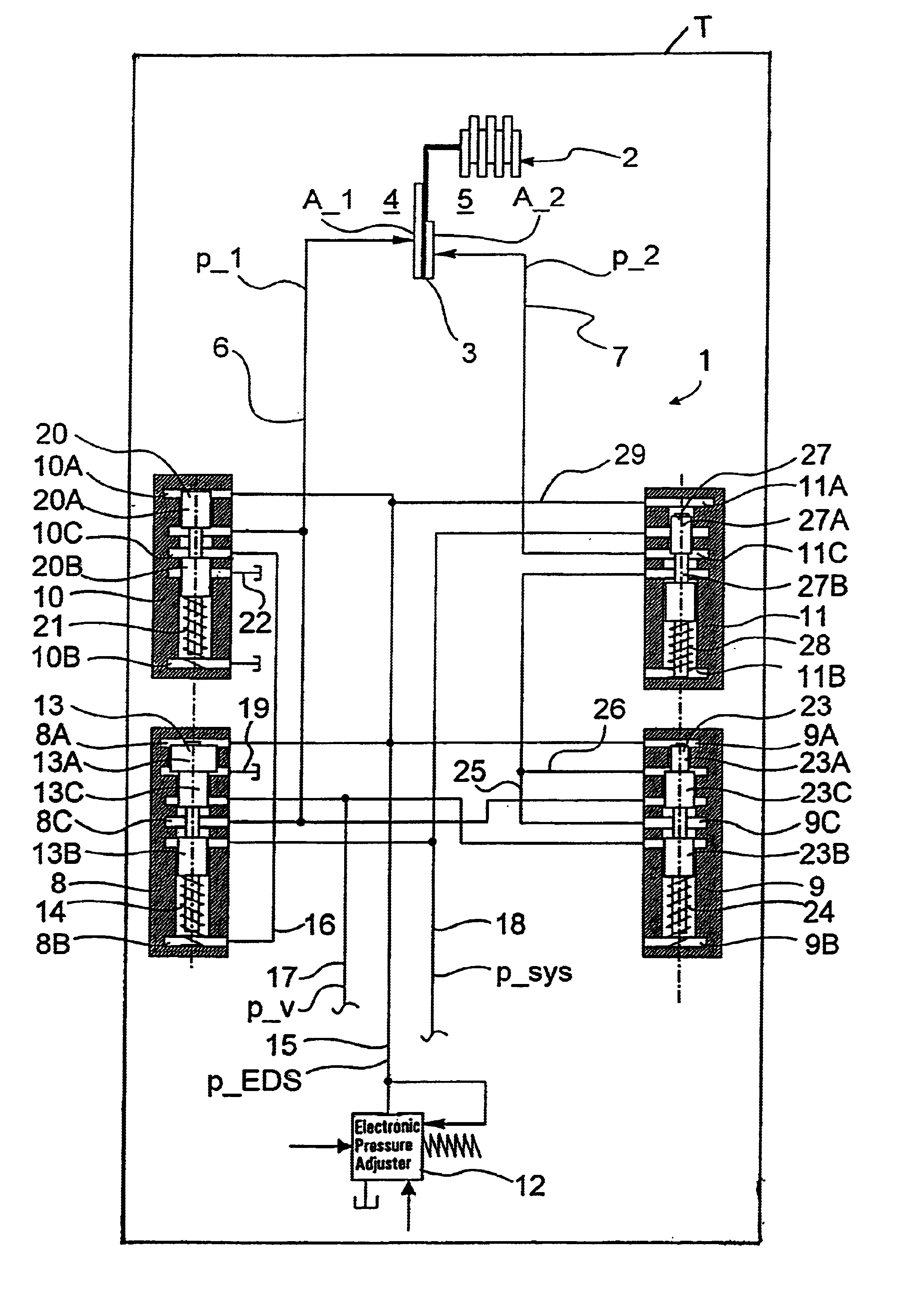
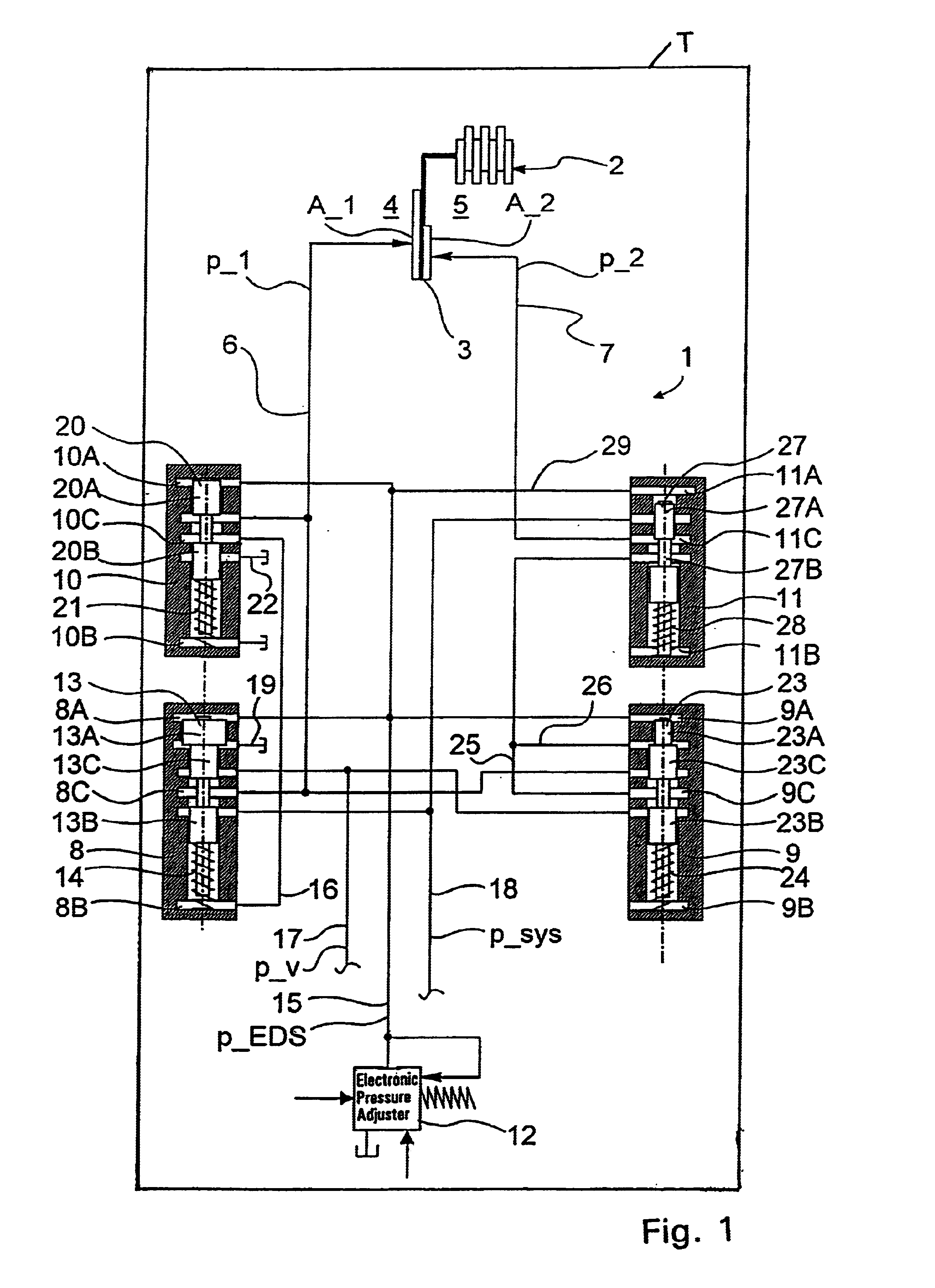
[0030]Referring to FIG. 1 and FIG. 3, respectively, they show a device 1, 1′ for control of a hydraulically actuatable clutch 2 designed as a multi-disc clutch of a powershift transmission T of a motor vehicle.

[0031]The clutch 2 has a clutch piston 3, only symbolically shown in the figures, which is displaceably movable in a cylinder (not shown in detail), and which defines, with a first surface A_1, a piston space 4 pressurizable with hydraulic medium, and with a second surface A_2 lying opposite and of smaller size a reset space 5. The piston space 4 and the reset space 5 are symbolically indicated in FIG. 1 and FIG. 3 by the reference numerals thereof.

[0032]To actuate the clutch 2, the piston space 4 can be pressurized with a hydraulic medium, as a pressure medium which, via a line 6, can be passed thereinto with a pressure p_1 and again removed therefrom. To move the clutch piston 3 from a shifting position back to an idle position, one hydraulic reset device is provided in a ma...


PUM


Abstract

A device for control of a hydraulically actuatable shifting element of a motor vehicle transmission, having one clutch piston which defines, with a first surface, a hydraulically pressurizable piston space and, with a second surface of different size, a hydraulically pressurizable reset space and comprising a first clutch valve associated with the piston space, a second clutch valve associated with the reset space and a holding valve associated with the reset space. The valves can be moved according to a control pressure adjusted by a pressure adjuster, a change between a pressurization of the clutch piston on the piston space side and on the reset space, side being performed as a control function so that the clutch piston on its surface facing the reset space is pressurized in an unshifted state of the shifting element and is discharged in a shifted state of the shifting element.

Description

FIELD OF THE INVENTION[0001]The invention relates to a device for control of a hydraulically actuatable shifting element of a motor vehicle transmission, specially of a powershift transmission.BACKGROUND OF THE INVENTION[0002]Powershift transmissions in which a change in ratio or a change in gear often results as an overlapping shift with direct torque transfer between two shifting elements, but also double-clutch transmissions, require accurate regulation. For example, in an overlapping shift, the moment of torque transfer must be very precisely determined according to the driving situation and load so as to satisfy the requirements of riding comfort and driving dynamics.[0003]The shifting of a shifting element designed, for example, as a multi-disc clutch of a power transmission, from an actuated to an unactuated state results in the practice by displacement of a double-acting clutch piston by means of a hydraulic medium, the clutch piston defining, with one first surface, a clutc...

Claims


Application Information

Patent Timeline
Patent Type & Authority Patents(United States)
IPC IPC(8): F16H61/02F16H63/30F16D25/00F16D25/12
CPCF16D25/12F16H63/3026F16H61/0206F16H2063/303
Inventor SCHMIDT, THILOGIERER, GEORGSTEINHAUSER, KLAUS
Owner ZF FRIEDRICHSHAFEN AG
Why Eureka
Try Eureka