
Pre-treatment liquid for use in preparation of an offset printing plate using direct inkjet CTP

a technology of offset printing and liquid treatment, which is applied in the direction of liquid soap, duplicating/marking methods, printing processes, etc., can solve the problems of high production cost, unstable, messy and environmentally harmful films, etc., and achieve stable ink dots, improve image quality, and improve the effect of plate preparation speed

Inactive Publication Date: 2005-06-14
HEWLETT PACKARD IND PRINTING LTD
View PDF31 Cites 50 Cited by
  • Summary
  • Abstract
  • Description
  • Claims
  • Application Information

AI Technical Summary

Benefits of technology

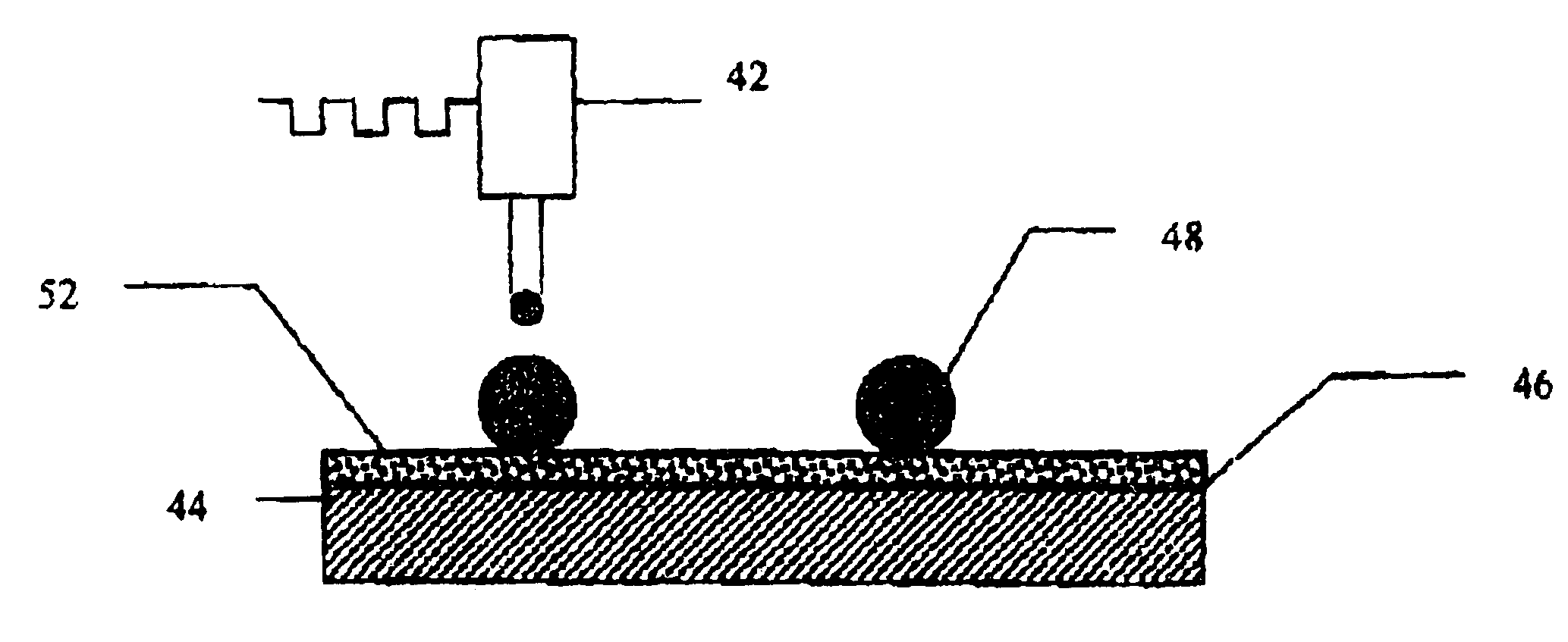
[0029]The inventors have found that the image quality on the plate can be further improved, and the speed of plate preparation can be elevated by treating the anodized aluminum plate with a pre-treatment liquid that interacts immediately, both chemically and physically with the CTP liquid to form a stable image with no clustering phenomenon. According to the present invention the surface of a substrate such as, bare anodized aluminum with no pre-coating, is treated with a pre-treatment solution prior to the deposition of the ink on the surface.
[0030]The inventive pre-treatment liquid is an aqueous and / or alcoholic solution or an oil in water emulsion (where the oil is a non-miscible swelling reagent) containing a polyvalent metal salt, and at least one of an organic swelling reagent and / or a coalescence reagent. The pre-treatment liquid is applied to form a thin, homogenous layer of approximately 4 μm to the entire upper surface of the recording plate. The swelling reagent and / or the coalescence reagent and the polyvalent metal cations, in the pre-treatment liquid, are physically well localized in the porous structure of the plate's surface. After partial drying of the pre-treated anodized aluminum plate, CTP liquid is deposited onto the surface to form an image. The CTP liquid solids react with the pre-treatment liquid and are, therefore, chemically bound to the surface. This allows all data to be deposited in a single pass of the inkjet head without the problem of clustering. The solids in the CTP liquid precipitate in response to the localized cations deposited in the pre-treatment, and form interactions above and in the pores of the surface of the plate to give a mechanically stable ink dot. After post-print drying at temperatures high enough to evaporate the swelling reagent and / or the coalescence reagent, the ink dot remains mechanically bound to the surface of the media.

Problems solved by technology

Not only are these films a source of expense, but the most widely used films are based on silver chemistry whereby the exposure and handling of the film must be in a light-excluding environment.
In addition, the exposed film must be processed with chemical solutions, which are unstable, messy and environmentally problematic.
In general, such plates still need processing by solution although attempts are being made to develop computer-to-plate systems that are processless.
All of these inventions involve multiple layered plates that are expensive to produce.
Also, it is difficult to maintain a consistent standard of quality from plate to plate.
Moreover, they utilize laser imaging systems which are in themselves costly.
This has limited run length capability, similar to other spark discharge and laser ablation techniques.
This process is impractical because the water-soluble or alkali-soluble coating used in the ink-absorbing layer has serious disadvantages since the ink imaged photopolymer sits on top of this layer.
On typical offset press, the use of an aqueous fountain solution would be disastrous for this plate.
Additionally, the ink absorbing properties of this film limit control of dot or image formation and the resolution of fine details is still problematic.
The disadvantage of this method is that after masking the imaged area, the plate needs to be exposed and developed.
One problem of such an approach is the difficulty of obtaining sufficiently good adhesion of the waxes of the ink to the plate to run multiple impressions during lithographic printing.
However, these prior arts attempts to use the inkjet process for imaging plates, remain with difficulties in producing satisfactory quality, run length and plate-making speed, because of problems of spreading and clustering.
Creating an image on a highly hydrophilic, water receptive surface of an anodized aluminum offset plate with water-based liquid by means of an ink jet process, is very problematic.
Therefore, it is almost impossible to create a sharp image on the plate.
Both water-based and solvent-based inks have problems of spreading of the liquid on the high surface energy hydrophilic plate surface due to the properties needed to jet the ink.
In addition, water-based inks, due to the hydrophobic nature of the plate's coating, tend to create a clustering phenomenon at the dark tone areas of the image (shadows).
This makes the plate preparation time quite long.

Method used


Image

  • Pre-treatment liquid for use in preparation of an offset printing plate using direct inkjet CTP
  • Pre-treatment liquid for use in preparation of an offset printing plate using direct inkjet CTP
  • Pre-treatment liquid for use in preparation of an offset printing plate using direct inkjet CTP

Examples


example 1

[0054]An offset plate was coated using a rubbing motion with a coating solution consisting of 5% butyl carbitol, 3% N-methyl pyrrolidone, 92% deionized water and phosphoric acid, which was added to provide a pH between 1 to 2, and dried at 50° C. for 30 sec. The plate was then placed on an XY bed where it was imaged, in 600 dpi resolution, (using the inkjet print head described in EP640481 filled with CTP liquid described in Israeli patent application no. 132789) to produce a very sharp 600 dpi quality image by single pass of the head, with no clustering phenomenon. The plate was then coated with acidified gum arabic.

example 2

[0055]An offset plate was coated using a rubbing motion with a coating solution consisting of 13% Zinc acetate, 3% Calcium chloride, 5% Propyl acetate, 5% Butyl carbitol, 40% ethanol, 34% deionized water, and dried at 50° C. for 30 sec. The plate was then placed on an XY bed where it was imaged, in 600 dpi resolution, (using the inkjet print head described in EP640481 filled with CTP liquid described in Israeli patent application no. 132789) to produce a very sharp 600 dpi quality image by single pass of the head, with no clustering phenomenon. The plate was then coated with acidified gum arabic.

example 3

[0056]An offset plate was coated using a rubbing motion with a coating solution consisting of 13% Zinc acetate, 3% Calcium chloride, 5% Butyl lactate, 5% Butyl carbitol, 32% Ethanol and 42% of deionized water, and dried at 50° C. for 30 sec. The plate was then placed on an XY bed where it was imaged, Dpi 600 dpi resolution, (using the inkjet print head described in EP640481 filled with CTP liquid described in Israeli patent application no. 132789) to produce a very sharp 600 dpi quality image by single pass of the head, with no clustering phenomenon. The plate was then coated with acidified gum arabic.


PUM

PropertyMeasurementUnit
Lengthaaaaaaaaaa
Fractionaaaaaaaaaa
Fractionaaaaaaaaaa

Abstract

A method of making a printing plate in which the uncoated surface of a substrate is treated with a pre-treatment solution prior to the deposition of ink on the surface. The pre-treatment liquid comprises a polyvalent metal salt, and at least one of an organic swelling reagent and / or a coalescence reagent. The pre-treatment liquid is applied to form a thin, homogenous layer of approximately 4 μm to the entire upper surface of the recording plate. The swelling reagent and / or the coalescence reagent and the polyvalent metal cations are physically well localized in the porous structure of the plate's surface. After partial drying of the pretreated anodized aluminum plate, CTP liquid is deposited onto the surface to form an image. The CTP liquid solids react with the pre-treatment liquid and are, therefore, chemically bound to the surface. This allows all data to be deposited in a single pass of the inkjet head without the problem of clustering.

Description

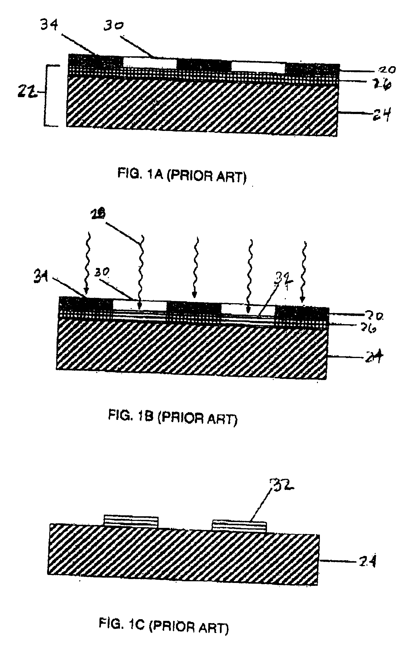
FIELD OF THE INVENTION[0001]The present invention relates to a plate making method, and more particularly, to a surface treatment of the plate surface, prior to the deposition of ink on the media.BACKGROUND OF THE INVENTION[0002]Offset lithographic printing has remained a most popular method of printing for many years. An important reason for this is the relative ease with which offset lithographic printing plates can be produced. Currently, the most widely used method for plate preparation has remained that which utilizes specially prepared masking films through which pre-sensitized printing blanks are selectively hardened or softened (according to the chemistry of the plate) by exposure to ultra violet light. The plate then undergoes a development process, during which the more soluble regions of the plate are washed away. A detailed description of the system and the plates used can be found in Chapter 20 of the book Printing Materials: Science and Technology by Bob Thomson 1998, ...

Claims


Application Information

Patent Timeline
IPC IPC(8): B41C1/10B41N3/03
CPCB41N3/03B41C1/1066
Inventor NITZAN, BOAZFRENKEL, MOSHE
Owner HEWLETT PACKARD IND PRINTING LTD
Learn More