Thermally imageable elements imageable at several wavelengths

a technology of imageable elements and wavelengths, applied in the field of lithographic printing, can solve the problems of time-consuming process, inability to easily image by imaging devices, and small change in mask dimension

Inactive Publication Date: 2005-06-21
KODAK POLYCHROME GRAPHICS
View PDF18 Cites 42 Cited by
  • Summary
  • Abstract
  • Description
  • Claims
  • Application Information

AI Technical Summary

Benefits of technology

[0019]When used as photothermal conversion materials in imageable elements, these infrared absorbing compounds provide an efficient method for forming images by direct digital imaging using either 800 nm±50 nm radiation or 1050 nm±50 nm radiation. Becau...

Problems solved by technology

This is a time-consuming process.
In addition, the mask may change slightly in dimension due to changes in temperature and humidity.
Thus, the same mask, when used at different times or in different environments, may give different results and could cause registration problems.
Imageable elements that contain these materials are sensit...

Method used


Image

  • Thermally imageable elements imageable at several wavelengths
  • Thermally imageable elements imageable at several wavelengths
  • Thermally imageable elements imageable at several wavelengths

Examples


example 1

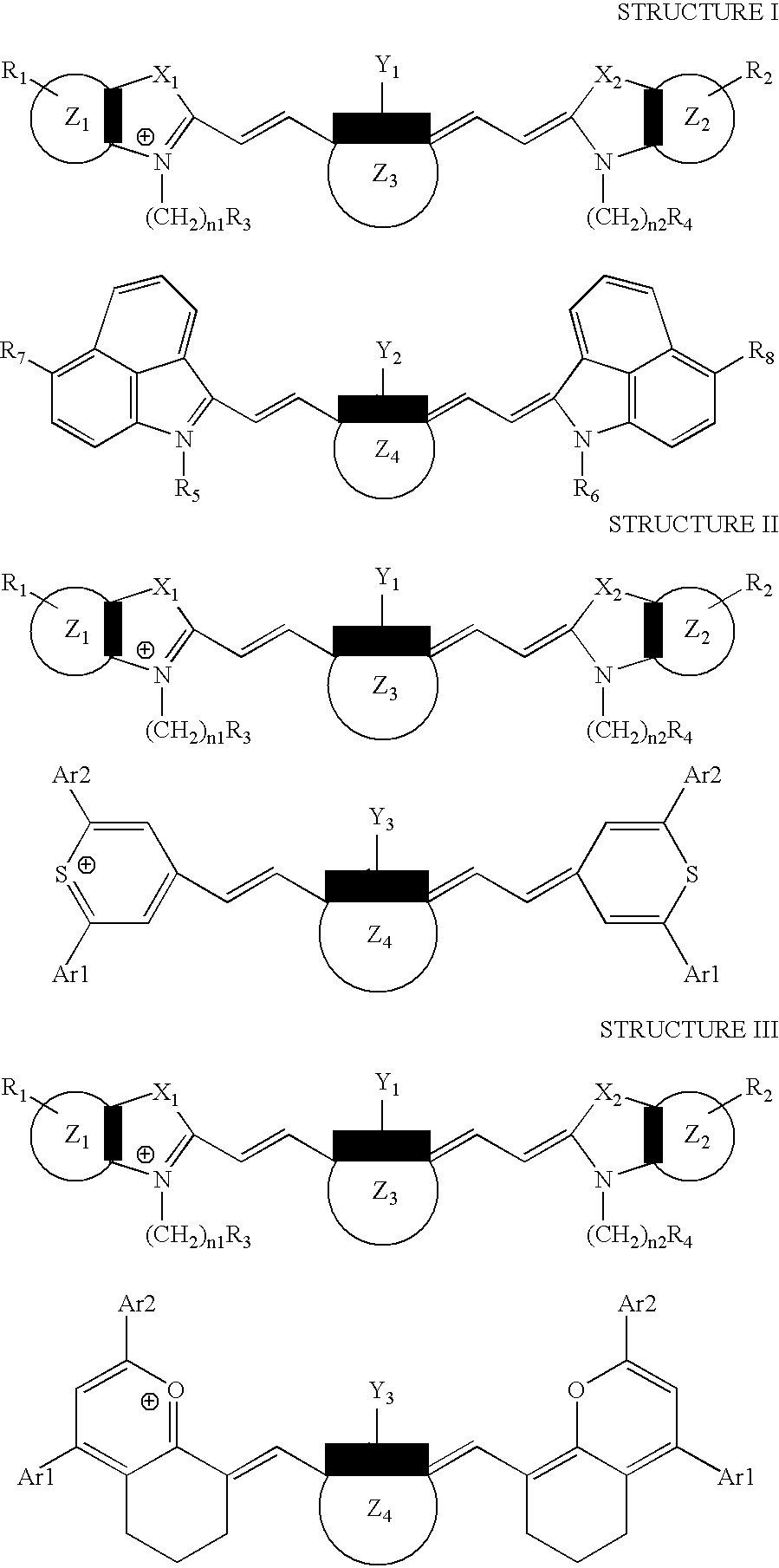
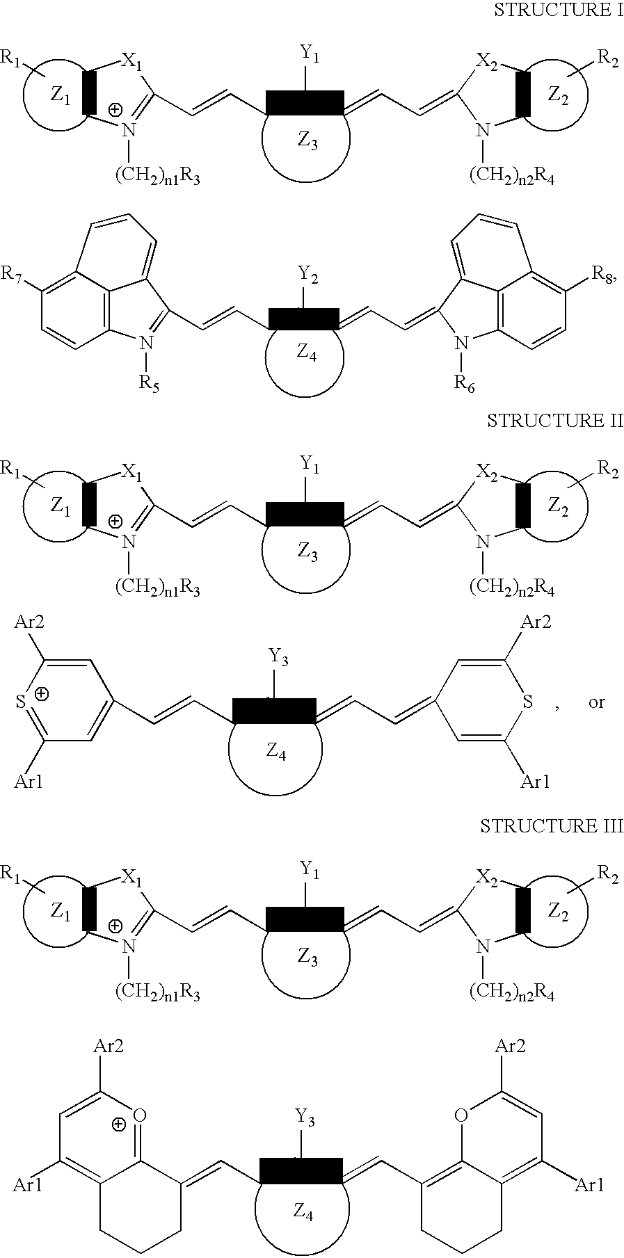
[0097]This example illustrates the preparation of (1-butyl-2-[2-[3-[(1-butyl-6-chlorobenz[cd]indol-2(1H)-ylidene)ethylidene]-2-chloro-1-cyclohexen-1-yl]ethenyl]-6-chlorobenz[cd]-indolium, compound with, 2-[2-[2-chloro-3-[(1,3-dihydro-1,1,3-trimethyl-7-sulfo-2H-benz[e]indol-2-ylidene)ethylidene]-1-cyclohexen-1-yl]ethenyl]-1,1,3-trimethyl-7-sulfo-1H-benz[e]indolium inner salt, a compound of the invention.

[0098]0.90 g of KAN707012 dye was dissolved in 10 g of water and 20 g of methanol. A solution of 0.70 g of IR 1048 dye in 10 g of water and 20 g of methanol was slowly added to this solution with stirring. The reaction mixture was stored in the dark at room temperature overnight. The resulting precipitate was filtered off, washed with 50 ml of acetone, and dried at ambient temperature for 12 hours. Yield: 1.5 g.

[0099]The absorption spectrum of the resulting compound showed maxima at 807 nm and 1003 nm.

example 2

[0100]A coating solution was prepared by dissolving 0.052 g of the compound prepared in Example 1, 1.05 g of LB6564, 0.30 g of LB744, 0.030 g of BASONYL® Violet 610, and 0.004 g of BYK 307 into 22 g of 1,1,3,3-tetramethylurea (Aldrich, Milwaukee, Wis., USA).

[0101]The coating solution was coated onto an electrochemically grained and anodized aluminum substrate post-treated with polyvinylphosphonic acid and the resulting element was dried at about 100° C. for about 1 minute on a conveyor oven. Dry coating weight: about 1.5 g / m2 (140 mg / ft2).

[0102]The resulting imageable element was imaged on a CREO Trendsetter 3244x image setter (CreoScitex, Burnaby, British Columbia, Canada) at 830 nm at a laser power of 15 W and a drum speed of 113 rpm (exposure energy 300 mJ / cm2). An additional imageable element was imaged in a Barco Crescent 42 Imagesetter (Barco Graphics, Vandalia, Ohio, USA) with 1064 nm IR laser at a laser power of 255 units. The resulting imaged imageable elements were develop...

example 3

[0103]This example illustrates the preparation of 4-[2-[3-[(2,6-diphenyl-4H-thiopyran-4-ylidene)ethylidene]-2-phenyl-1-cyclohexene-1-yl]ethenyl]-2,6-diphenylthiopyrylium compound with, 2-[2-[2-chloro-3-[(1,3-dihydro-1,1,3-trimethyl-7-sulfo-2H-benz[e]indol-2-ylidene)ethylidene]-1-cyclohexen-1-yl]ethenyl]-1,1,3-trimethyl-7-sulfo-1H-benz[e]indolium inner salt, a compound of the invention.

[0104]0.25 g of KAN707012 dye was dissolved in 2.8 g of water and 5.6 g of methanol. A solution of 0.20 g of IR 1040 dye in 2.8 g of water and 5.6 g of methanol was slowly added to this solution with stirring. The reaction mixture was stored in the dark at room temperature overnight. The resulting precipitate was filtered off, washed with 50 ml of acetone, and dried at ambient temperature for 12 hours. Yield: 0.4 g.

[0105]The absorption spectrum of the resulting compound showed maxima at 807 nm and 995 nm.


PUM

PropertyMeasurementUnit
Nanoscale particle sizeaaaaaaaaaa
Wavelengthaaaaaaaaaa
Spectrumaaaaaaaaaa

Abstract

Infrared absorbing compounds that absorb at 800 nm±50 nm and at 1050 nm±50 nm, the two different regions of the infrared spectrum typically used for imaging, are disclosed. Thermally imageable elements that comprise these infrared absorbing compounds can be imaged with radiation in either of these two regions of the infrared spectrum. The elements are especially useful as lithographic printing plate precursors.

Description

FIELD OF THE INVENTION[0001]The invention relates to lithographic printing. In particular, this invention relates to thermally imageable elements, useful as printing plate precursors, that can be imaged with either of two different regions of infrared radiation.BACKGROUND OF THE INVENTION[0002]In lithographic printing, ink receptive regions, known as image areas, are generated on a hydrophilic surface. When the surface is moistened with water and ink is applied, the hydrophilic regions retain the water and repel the ink, and the ink receptive regions accept the ink and repel the water. The ink is transferred to the surface of a material upon which the image is to be reproduced. Typically, the ink is first transferred to an intermediate blanket, which in turn transfers the ink to the surface of the material upon which the image is to be reproduced.[0003]Imageable elements useful as lithographic printing plate precursors typically comprise a top layer applied over the hydrophilic surf...

Claims


Application Information

Patent Timeline
IPC IPC(8): C09B69/00C09B69/02
CPCC09B69/02C09B23/0008C09B23/0033C09B23/0041C09B23/08C09B23/086C09B23/0066Y10S430/145Y10S430/146
Inventor KORIONOFF, LEETAO, TINGRAY, KEVIN B.
Owner KODAK POLYCHROME GRAPHICS
Why Eureka
Try Eureka