Composite material including copper and cuprous oxide and application thereof

a technology of copper and cuprous oxide, applied in the field of composite materials, can solve the problems of increasing heat evolution, not suitable for the radiator of power semiconductor devices, copper does not solder well with silicon, etc., and achieves the effects of less coagulation of powder particles, and large particle diameter

Inactive Publication Date: 2005-06-21
HITACHI LTD
View PDF34 Cites 20 Cited by
  • Summary
  • Abstract
  • Description
  • Claims
  • Application Information

AI Technical Summary

Benefits of technology

[0043]Cu2O particles in the sintered body should be as fine as possible because their particle diameter affects the density, strength, and plastic workability of the composite material. The

Problems solved by technology

Unfortunately, copper is not suitable for the radiator of power semiconductor devices because it has a high thermal expansivity of 17×10−6/° C. and hence it does not solder well with silicon, whose thermal expansivity is 4.2×10⁻⁶/C.
A problem involved with recent electronic semiconductor elements is heat evolution, which increases as the degree of integration increases and the speed of operation increases.
Unfortunately, malfunction can be anticipated because of the difference the thermal expansivity between copper and silicon.
This device has the advantage of a high thermal con

Method used


Image

  • Composite material including copper and cuprous oxide and application thereof
  • Composite material including copper and cuprous oxide and application thereof
  • Composite material including copper and cuprous oxide and application thereof

Examples


example 1

[0066]Raw material powders used in this example are electrolytic copper powder (with a particle diameter of 75 μm or less) and Cu2O powder (with a particle diameter of 1-2 μm and a purity of 3N). They were mixed in a ratio shown in Table 1. The resulting mixture (1400 g) was thoroughly mixed for more than 10 hours in a dry pot mill containing steel balls. The resulting mixed powder was placed in a mold, 150 mm in diameter, and cold-pressed under a pressure of 400-1000 kg / cm2 depending on the Cu2O content. Thus, there were obtained preforms measuring 150 mm in diameter and 17-19 mm in height. The preforms were sintered in an argon atmosphere. The resulting sintered bodies were chemically analyzed, examined for structure, and measured for thermal expansivity, thermal conductivity, and Vickers hardness. Incidentally, sintering was carried out for 3 hours at 900-1000° C. depending on the Cu2O content. The thermal expansivity was measured in the range of room temperature to 300° C. by us...

example 2

[0072]The same procedure as in Example 1 was repeated except that mixing was carried out by using a V-mixer. There was obtained a sintered body composed of Cu and 55 volt of Cu2O. This sintered body was examined for microstructure, thermal expansivity, and thermal conductivity in the same way as in Example 1.

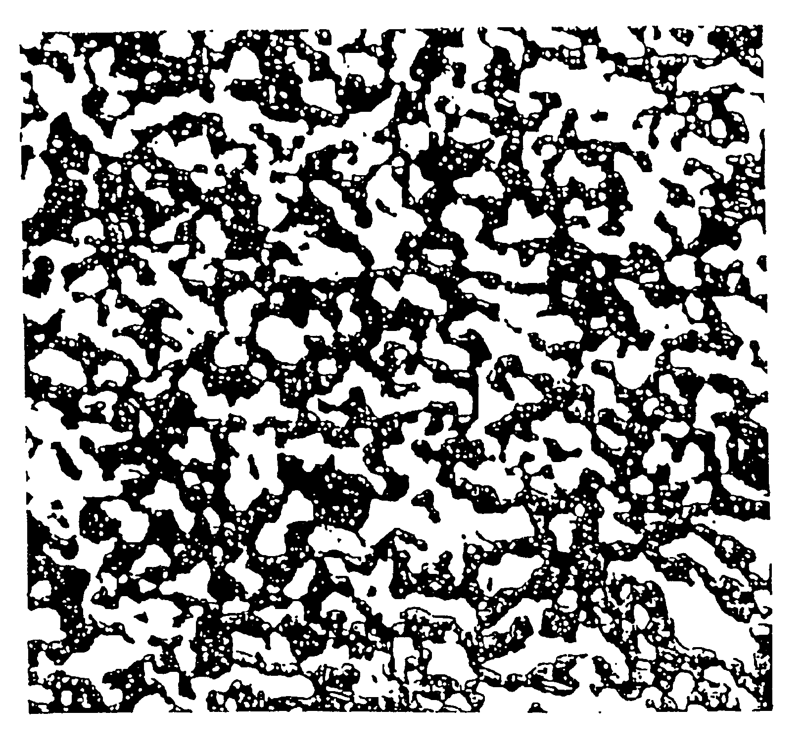
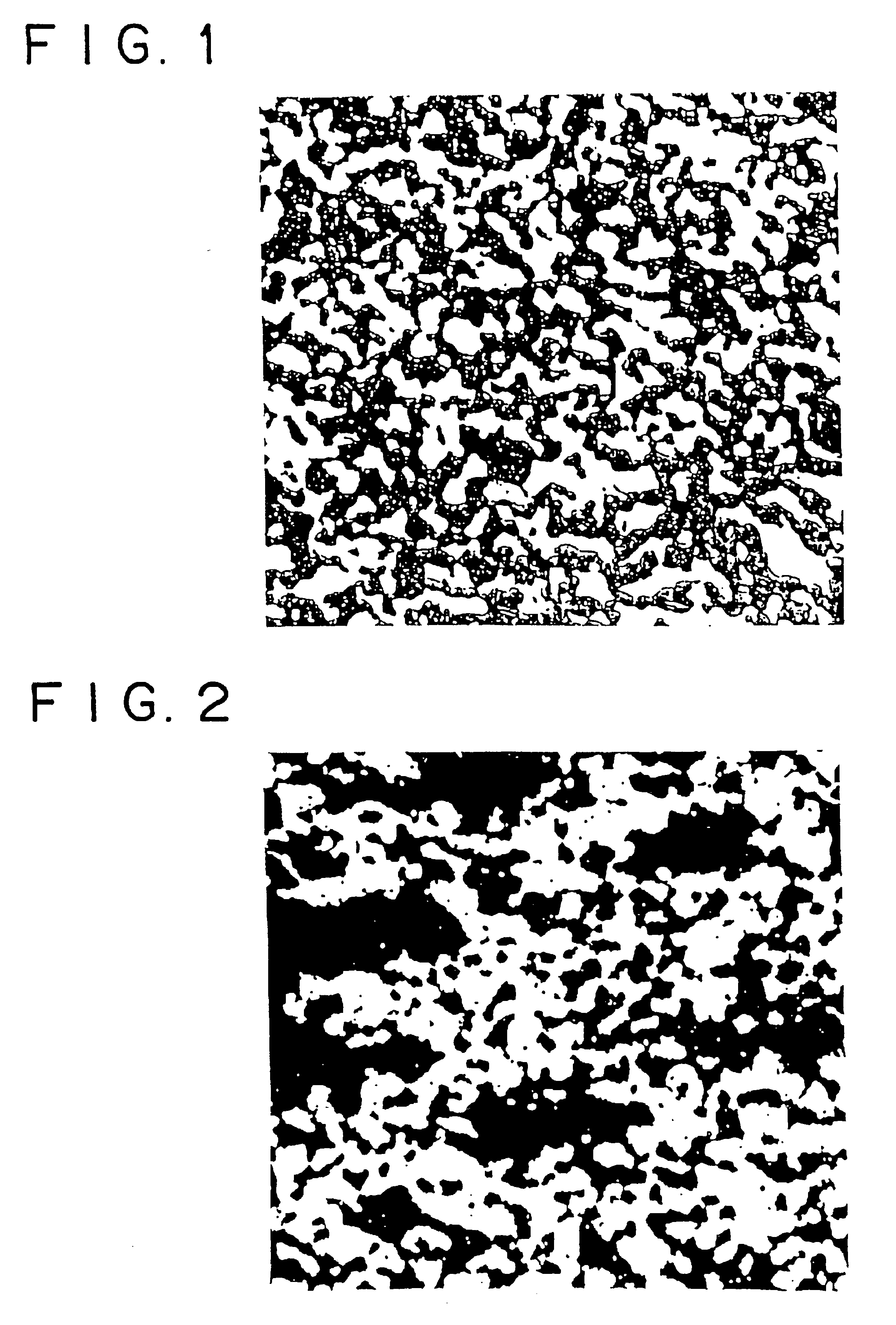
[0073]FIG. 2 is a photomicrograph (×300) of the sintered body composed of Cu and 55 volt of Cu2O. It is apparent from the photomicrograph that the microstructure contains Cu2O particles greatly varying in size. Large Cu2O particles are formed by coagulation during mixing in the V-mixer. The sintered body in this example is almost comparable in thermal expansivity and thermal conductivity to that of the same composition in which the Cu2O phase is uniformly dispersed in the Cu phase. However, the measured values vary from one position to another. It is noted that Cu2O particles are dispersed mostly in an irregular pattern as in FIG. 1, but they are in larger aggregates than those ...

example 3

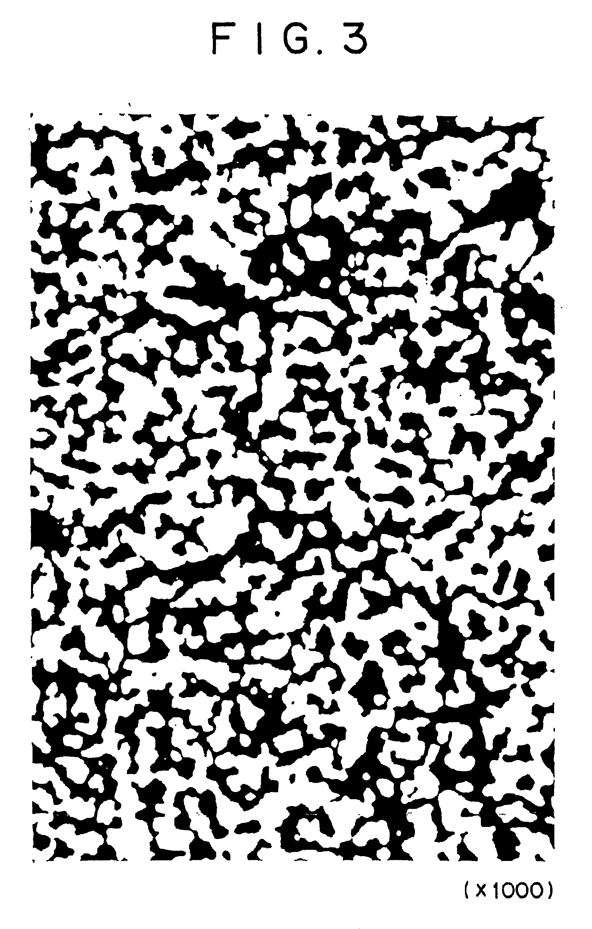
[0074]Raw material powders used in this example are electrolytic copper powder (with a particle diameter of 74 μm or less) and CuO powder (with a particle diameter of 1-2 μm and a purity of 3N). They were mixed to establish a composition of Cu and 22.4 volt of CuO. The resulting mixture (300 g) was thoroughly mixed by mechanical alloying for 25 hours in a planetary ball mill (120 mm in diameter) containing steel balls (8 mm in diameter). The resulting mixed powder was placed in a mold, 80 mm in diameter, and cold-pressed under a pressure of 1000 kg / cm2. Thus, there was obtained a preform. The preform was sintered in an argon atmosphere at 800° C. for 2 hours. The resulting sintered body was examined for structure, thermal expansivity, and thermal conductivity in the same way as in Example 1. It was also tested by X-ray diffractometry.

[0075]FIG. 3 is a photomicrograph (×1000) of the microstructure of the sintered body. It is apparent from the photomicrograph that Cu2O particles are f...


PUM

PropertyMeasurementUnit
Temperatureaaaaaaaaaa
Fractionaaaaaaaaaa
Thermal conductivityaaaaaaaaaa

Abstract

A composite material is provided, which has a low thermal expansivity, a high thermal conductivity, and a good plastic workability, which composite material may be applied to semiconductor devices and many other uses. The composite material is composed of metal and inorganic particles having a smaller coefficient of thermal expansion than the metal. It is characterized in that the inorganic particles are dispersed in such a way that 95% or more of them (in terms of their area in cross-section) form aggregates of complex configuration joined together. The composite material contains 20-80 vol % of copper oxide, with the remainder being copper. It has a coefficient of thermal expansion of 5×10⁻⁶ to 14×10−6/° C. and thermal conductivity of 30-325 W/m·K in the range of room temperature to 300° C. It is suitable for the radiator plate of semiconductor devices and the dielectric plate of electrostatic attractors.

Description

TECHNICAL FIELD[0001]The present invention relates to a composite material with low thermal expansivity and high thermal conductivity, to a process for production thereof, and to applications thereof such as semiconductor devices.BACKGROUND ART[0002]Power electronics include a technique which deals having a with power electronic devices to convert and a control electric power and energy, power electronic devices used in on-off mode, and a power conversion system as its application technique.[0003]Conversion of electric power calls for a variety of power semiconductors with switching capability. These semiconductors in practical use include rectifier diodes (with a pn Junction for current flow in only one direction), and thyristors, bipolar transistors, and MOSFETs (with a combination of pn junctions). Recently developed ones include insulated gate bipolar transistors (IGBT) and gate turn-off thyristors (GTO) which perform switching in response to gate signals.[0004]These power semic...

Claims


Application Information

Patent Timeline
IPC IPC(8): B22F1/00C22C32/00C22C29/00C22C29/12H01L23/373H01L21/68H01L21/67H01L23/34C22C1/05B22F1/06C22C1/10
CPCB22F1/0007C22C32/0021H01L21/6835H01L23/3733H01L24/32C22C29/12H01L2924/1305H01L24/45H01L2224/32225H01L2224/45124H01L2224/45144H01L2224/48091H01L2224/48247H01L2224/48472H01L2224/49109H01L2224/49111H01L2224/73265H01L2924/01005H01L2924/01009H01L2924/01013H01L2924/01014H01L2924/01018H01L2924/01029H01L2924/01033H01L2924/01039H01L2924/01042H01L2924/01047H01L2924/0105H01L2924/01058H01L2924/01074H01L2924/01078H01L2924/01079H01L2924/01082H01L2924/01322H01L2924/10329H01L2924/13055H01L2924/13091H01L2924/14H01L2924/15153H01L2924/1517H01L2924/15312H01L2924/1532H01L2924/16195H01L2924/19043H01L2924/30105H01L2924/3011H01L2924/3511H01L24/48H01L24/49H01L2224/48227H01L2924/01006H01L2924/01019H01L2924/01023H01L2224/29111H01L2924/0132H01L2924/0133H01L2224/2919H01L2924/01028H01L2924/12041H01L2924/1301H01L2924/00014H01L2924/00H01L2924/00012H01L2924/3512H01L2924/15787H01L2924/30111H01L2924/181H01L2924/12042H01L2924/12036H01L24/73B22F1/06H01L23/36
Inventor KONDO, YASUOKANEDA, JUNYAAONO, TASUHISAABE, TERUYOSHIINAGAKI, MASAHISASAITO, RYUICHIKOIKE, YOSHIHIKOARAKAWA, HIDEO
Owner HITACHI LTD
Why Eureka
Try Eureka