[0008]The method according to the invention for the controlled switching off of an internal combustion engine with spark ignition is distinguished by the fact that as high as possible a
cylinder pressure can build up in the compression and working cycles while the internal combustion engine is slowing to a standstill. This can be achieved by opening the previously closed
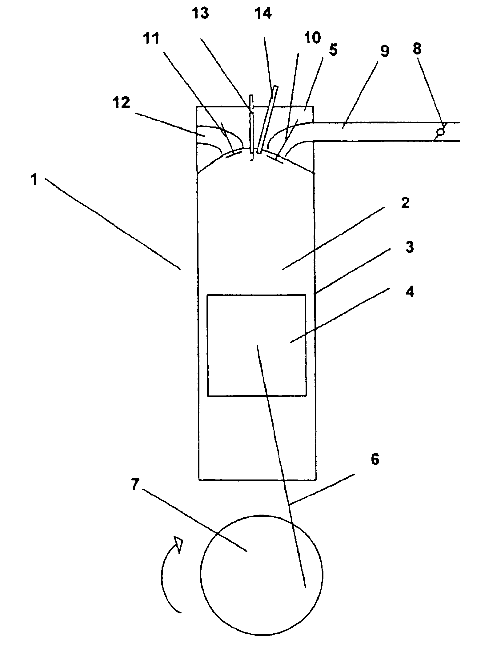
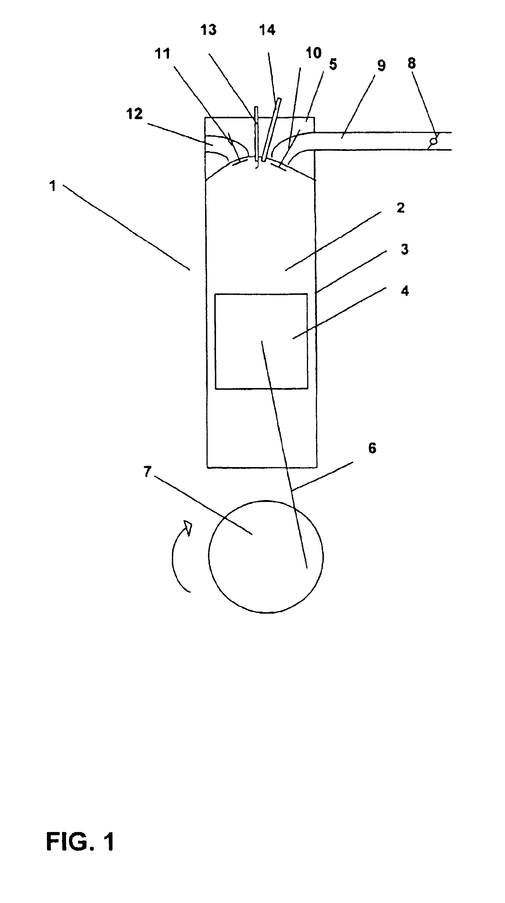
throttle valve at least once by a specified absolute rotational angle value after the spark ignition and
fuel supply have been switched off. In comparison with the customary method for switching off an internal combustion engine with the throttle valve closed, considerably more
fresh air is sucked into the cylinders during the switching off process in the method according to the invention. This means that the
cylinder pressure is increased considerably during the remaining compression cycles while the internal combustion engine is slowing to a standstill, in comparison with the cylinder pressure of an internal combustion engine which slows to a standstill with the throttle valve closed. Customary values here are, for example, 5 bar cylinder pressure with the throttle valve closed, compared with, for example, 20 bar cylinder pressure with the throttle valve completely open. The increased cylinder pressure results in higher gas forces. In contrast, the frictional forces change only slightly. The ratio of gas forces to frictional forces therefore becomes greater. The gas forces are dependent on the
crank angle. They reach their maximum at the respective
top dead center (
high pressure TDC). The
force equilibrium of the gas forces of the expansion cylinder and the compression cylinder lies at approximately 90°
crank angle after TDC (in relation to the expansion cylinder). This angular position is an advantageous switching off position, as it favors the subsequent re-starting operation. High gas forces, therefore, favor a switching off position which is suitable for direct starting. Moreover, it is also of
advantage that, with the throttle valve open, products of combustion which may possibly still be present are removed from the combustion chambers of the internal combustion engine by the
fresh air flowing into the internal combustion engine. This ensures that sufficient
oxygen is available for combustion of the fuel in the case of a direct starting operation comprising the injection of fuel into a
combustion chamber and ignition of the fuel / air mixture which is produced.
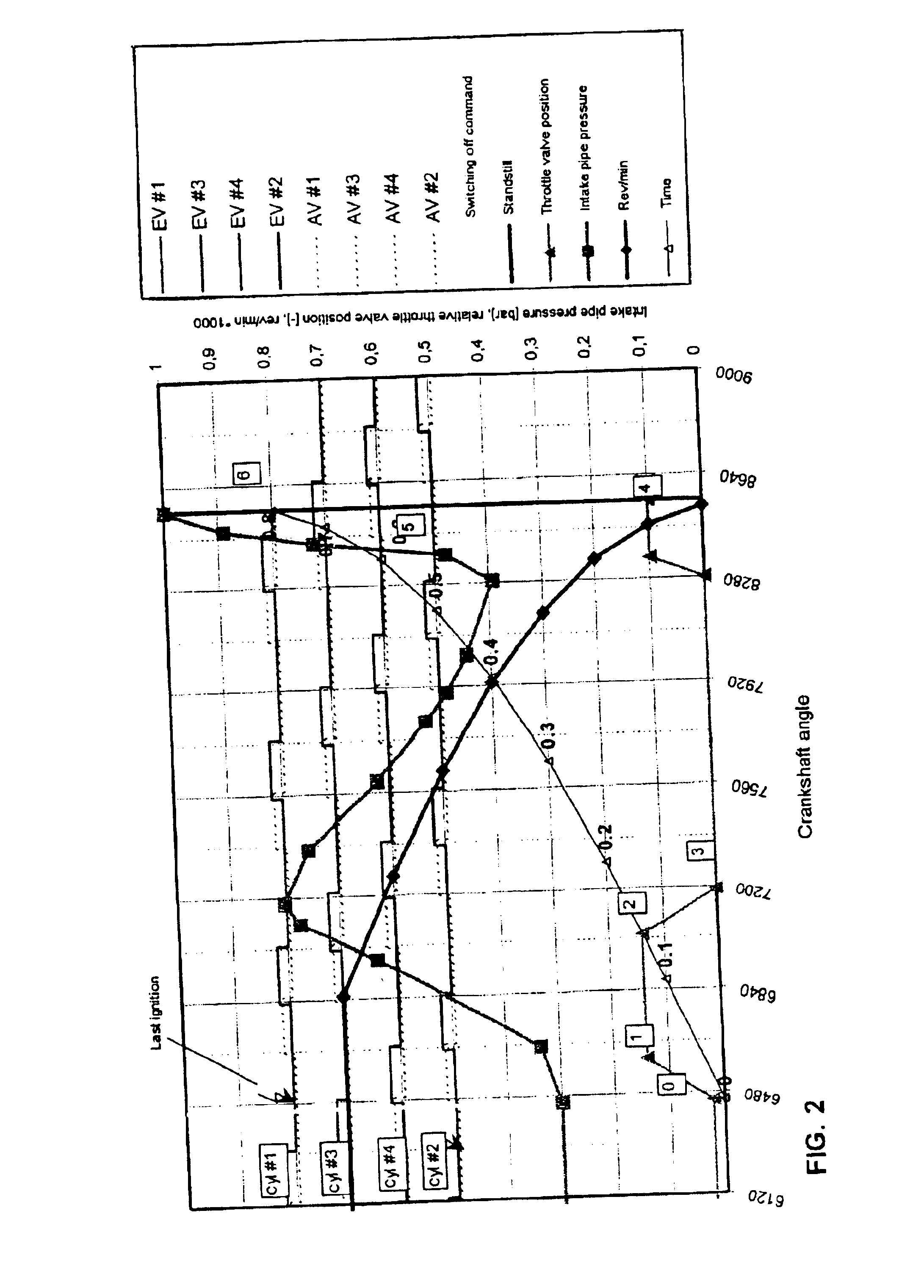
[0010]If the throttle valve is open while the internal combustion engine is slowing to a standstill, this can result in comfort problems caused by the internal combustion engine shaking or bucking. In one preferred refinement of the invention, the throttle valve is opened for only a short time after the engine has been switched off, in order to flush the cylinders with fresh air. Afterward, the throttle valve is closed at least once while the engine is slowing to a standstill, so that the internal combustion engine slows to a standstill more gently. In good time, before the internal combustion engine comes to a complete standstill, the throttle valve is opened once more, to ensure that the engine comes to a controlled standstill. Simultaneously, the supply of fresh air into the combustion chambers is maximized.
[0011]According to one development of the invention, a rotational speed
signal is used to actuate the throttle valve. While the internal combustion engine is slowing to a standstill, it is possible in this way to open or close the throttle valve, for example if a specific rotational speed is undershot. A method of the abovedescribed type can thus be realized using simple means.
[0013]In one preferred embodiment of the invention, the rotational angle
signal of the
crankshaft or
camshaft is used to actuate the throttle valve. If the respective rotational angle
signal is subjected to integration, the number of
camshaft or
crankshaft rotations, for example, after the last ignition can be ascertained. In this way, for example, the opening or closing of the throttle valve can be actuated after a predetermined number of revolutions. The simple implementation of the method, without additional sensors, etc. being required, is also advantageous here.
[0014]As already stated, it is, furthermore, advantageous if the throttle valve is opened again shortly before the internal combustion engine comes to a standstill. Firstly, in order that the internal combustion engine comes to a standstill in a controlled manner, it is advantageous to open the throttle valve during the intake process of the cylinder which later, when the engine is stationary, becomes the last compression cylinder. Secondly, it is advantageous to open the throttle valve during the intake process of the cylinder which later, when the engine is stationary, becomes the last expansion cylinder to achieve a maximum supply of fresh air for this cylinder, thus to have sufficient fresh air available in this cylinder for subsequent direct starting.

