Personal identification system

a technology of personal identification and finger veins, applied in the field of personal identification systems, can solve the problems of reducing the performance of identification, affecting the reproducibility of captured images, and unavoidable errors in imaging regions, so as to prevent the performance of identification from being degraded, improve reproducibility, and improve the effect of reproducibility

Inactive Publication Date: 2005-06-28
HITACHI LTD
View PDF18 Cites 24 Cited by
  • Summary
  • Abstract
  • Description
  • Claims
  • Application Information

AI Technical Summary

Benefits of technology

[0007]According to one aspect of the present invention, means described below is used for improving reproducibility. First means is an algorithm for correcting an error detected during image processing that is executed for matching an imaged finger blood vessel pattern with a registered pattern. This correction prevents the performance of identification from being degraded.
[0008]Second means is a three-dimensional imaging of a living body from various angles using a plurality of imaging devices. Even if a registered vein pattern was imaged from only one direction, that is, the registered pattern is two-dimensional data, the finger may be placed freely when imaged for identification. Therefore, even if there is an error in the imaging region, one of the plurality of images may be se

Problems solved by technology

However, there are some problems in implementing a personal identification system that uses finger vein patterns.
One of the problems is the reproducibility of a captured image.
Although a conventional personal identification system has positioning parts such as a pin or a grasping bar for stabilizing the imaging region, an error in the imaging region is unavoidable, for example, when a finger is rotated or moved in the plane or when a finger is rotated on its major axis.
Therefore, it is difficult to completely match a registered vein pattern with a vein pattern obtained at identification time, with the result that the performance of identification is reduced.
In particular, on a fully-non-contact

Method used


Image

  • Personal identification system
  • Personal identification system
  • Personal identification system

Examples


first embodiment

(First Embodiment)

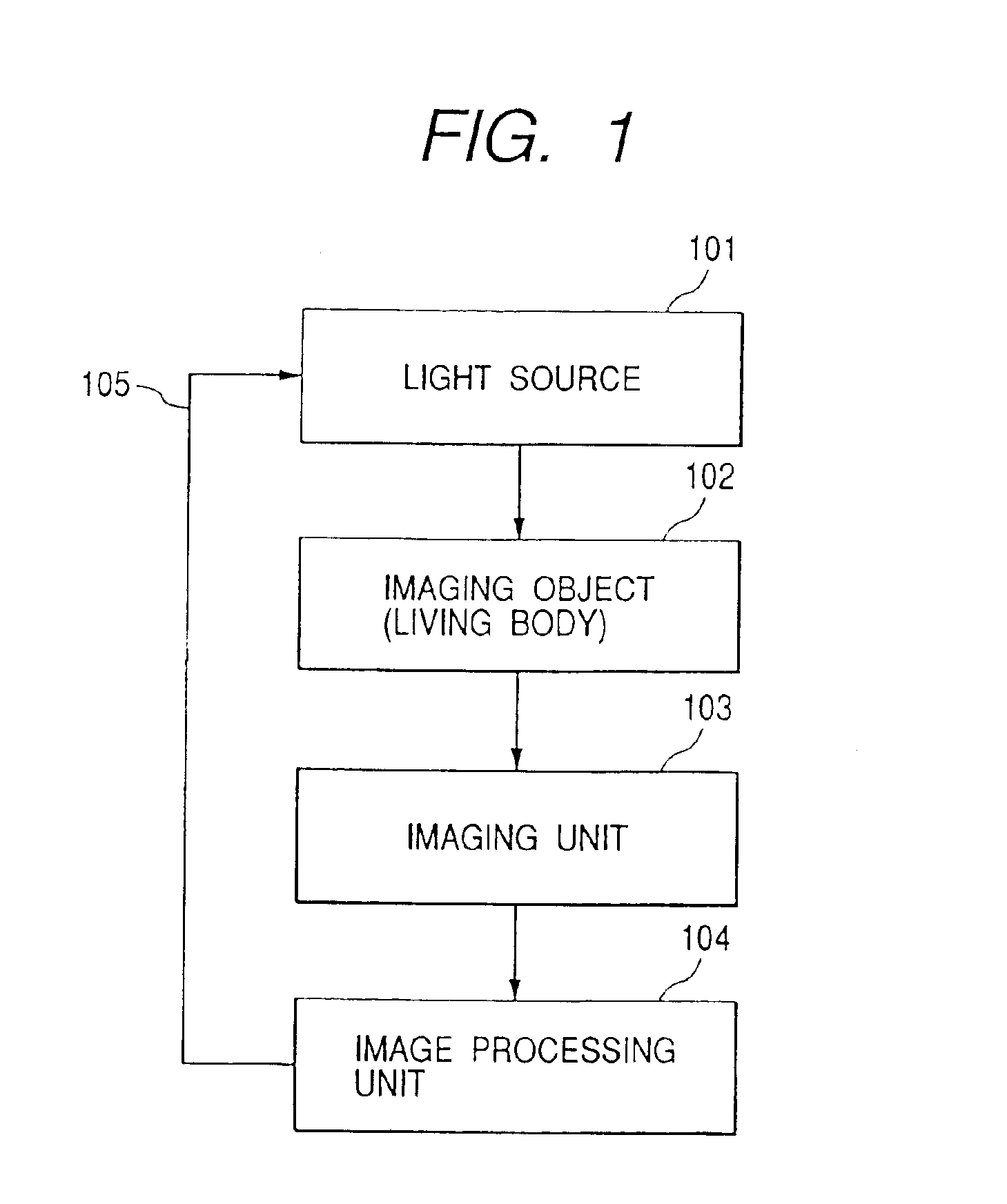
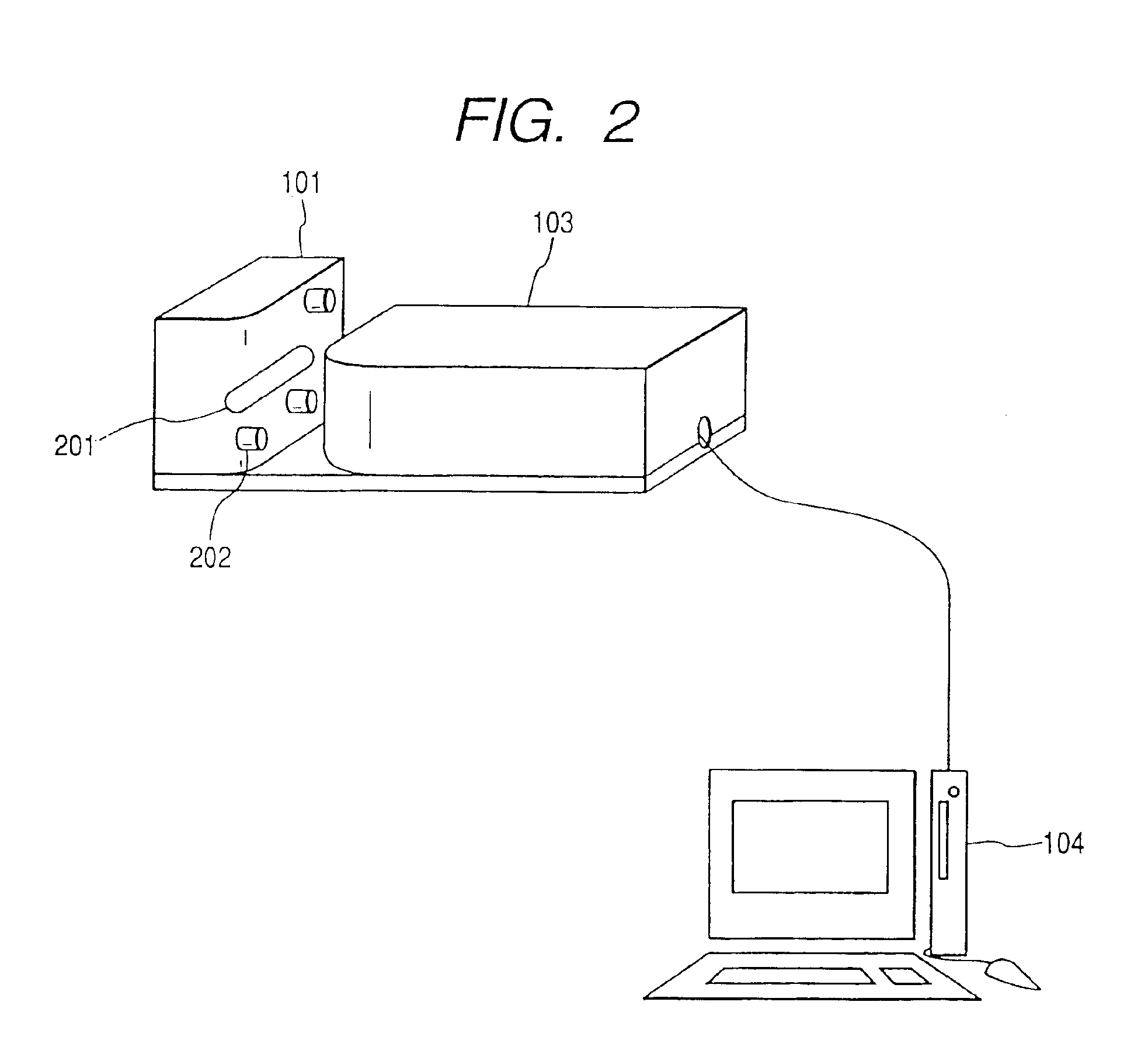
[0026]FIG. 1 is an example of the basic configuration of a personal identification system. FIG. 2 shows an embodiment of a personal identification system according to the present invention. The system comprises a light source unit 101 that shines a light on a finger, an imaging unit 103 that captures the image of a finger, and an imaging processing unit 104 that processes captured image data. As the light source, a semiconductor light source, such as an LED (Light Emitting Diode), is usually used because of its responsiveness and controllability. A CCD camera is used as the imaging unit. A personal computer is conveniently used as the imaging processing unit 104 that captures an image into the computer via the inter-face such as an image capture board. The imaging processing unit 104 performs processing necessary for identifying a captured image. Numeral 201 indicates a window through which a light from the light source transmits. An automatic shutter may be provid...

second embodiment

(Second Embodiment)

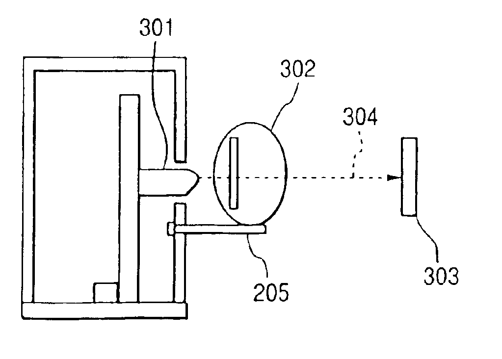
[0057]In the first embodiment, a finger is imaged with one CCD camera. A finger may also be imaged with a plurality of CCD cameras during authentication or image capturing to increase the performance of identification.

[0058]FIG. 5 shows the arrangement of this embodiment where a plurality of CCD cameras are used; that is, a light source 301, a finger 302, and CCD cameras (303-1-303-5) are arranged as shown. In this embodiment, a plurality of finger vein patterns are captured from a plurality of directions using a plurality of CCD cameras, and the pattern most similar to the registered vein pattern is selected for authentication. Alternatively, a plurality of vein patterns to be registered are captured and saved as three-dimensional data and, from these patterns, the pattern most similar to the vein pattern to be authenticated is selected for authentication. This method is particularly effective for preventing the performance of identification from being degraded w...

third embodiment

(Third Embodiment)

[0061]FIGS. 13A-13C are block diagrams showing in detail one example of blood vessel emphasizing processing (corresponds to blocks 1101-1103 in FIG. 11). When a finger image is received (block 1000 or 1004), edge detection processing is performed to detect the location of the finger edge (block 1300). Based on the detected edge location, image rotation processing is performed so that the image is rotated such that the finger is inclined at a fixed angle, typically, at an angle of 0 degree (block 1301). Blood pattern emphasizing processing is performed for the obtained image (block 1302).

[0062]For example, blood pattern enhancement processing is performed using a filter, such as the one shown in FIG. 13B, designed to remove high-frequency components in the major axis direction of the finger, and low-frequency components in the minor axis direction. Filtering may be done either by the convolution operation (formula 1) in the real space or by the multiplication operat...


PUM


Abstract

A personal identification system, which uses a vein pattern of a finger, optimizes the amount of light of a light source based on a captured finger image and emphasizes the vein pattern during image processing for identification.

Description

[0001]This application is a Continuation of nonprovisional application Ser. No. 09 / 954,067 filed Sep. 18, 2001, which was issued into U.S. Pat. No. 6,813,010 on Nov. 2, 2004. Priority is claimed based on U.S. application Ser. No. 09 / 954,067 filed Sep. 18, 2001, which claims the priority of Japanese application 2000-290325 filed on Sep. 20, 2000.BACKGROUND OF THE INVENTION[0002]The present invention relates to a technology for identifying a person using a living body, and more particularly to a technology for identifying a person using a finger vein pattern.[0003]Today, the typical personal identification technology is fingerprint identification. However, the problem is that other person's fingerprint is easily obtained, for example, a criminal's fingerprint is taken in the scene of a crime, and therefore a finger-print may be forged. This problem leads to the development of personal identification technologies other than fingerprint identification. For example, JP-A-7-21373, laid-op...

Claims


Application Information

Patent Timeline
IPC IPC(8): G06K9/00A61B5/117A61B10/00G06T1/00G06V10/10G06T7/00G06V40/14G06V40/145
CPCG06K9/00G06K9/20G06K9/00013G06K2009/00932G06V40/14G06V10/10G06V40/145G06F18/00
Inventor KONO, MIYUKIUMEMURA, SHIN-ICHIROMIYATAKE, TAKAFUMIHARADA, KUNIOITO, YOSHITOSHIUEKI, HIRONORI
Owner HITACHI LTD
Why Eureka
Try Eureka