Method and subsystem for processing signals utilizing a plurality of vibrating micromechanical devices

a micromechanical device and processing method technology, applied in relays, electrostatic generators/motors, generators/motors, etc., can solve the problems of large outperform of comparable filters implemented using transistor technologies, affecting the performance and affecting the processing efficiency of the signal processing system. , to achieve the effect of reducing the need for rf front-end power

Inactive Publication Date: 2005-07-12
RGT UNIV OF MICHIGAN
View PDF38 Cites 30 Cited by
  • Summary
  • Abstract
  • Description
  • Claims
  • Application Information

AI Technical Summary

Benefits of technology

[0028]An object of the present invention is to provide a method and subsystem for processing signals utilizi

Problems solved by technology

The need for passive off-chip components has long been a key barrier against communication transceiver miniaturization.
Due to higher quality factor Q, such technologies greatly outperform comparable filters implemented using transistor technologies, in insertion loss, percent bandwidth, and achievable rejection.
Being off-chip components, the above mechanical devices must interface with integrated electronics at the board level, and this constitutes an important bottleneck against the miniaturization of super-heterodyne transceivers.
Unfortunately, without adequate front-end selectivity, such approaches have suffered somewhat in overall performance, to the point where they so far are usable only in less demanding applications.
Like a single transistor, a single mechanical link does not possess adequate processing power for most applications.
As tank Q decreases, insertion loss increases very quickly, too much

Method used


Image

  • Method and subsystem for processing signals utilizing a plurality of vibrating micromechanical devices
  • Method and subsystem for processing signals utilizing a plurality of vibrating micromechanical devices
  • Method and subsystem for processing signals utilizing a plurality of vibrating micromechanical devices

Examples


Embodiment Construction

)

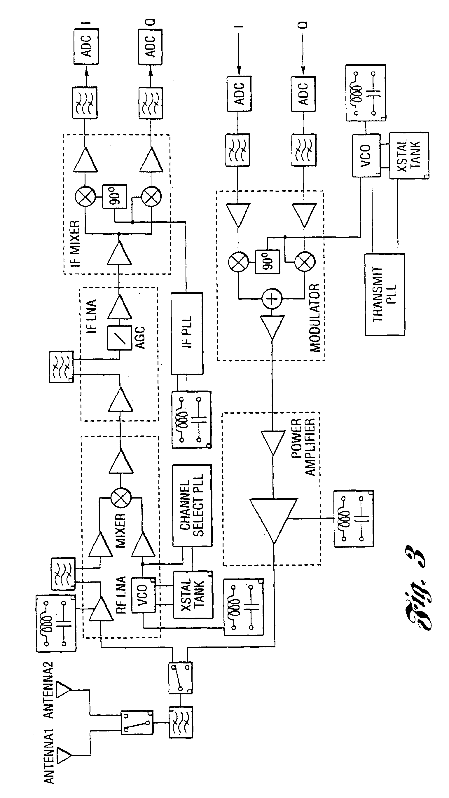
[0067]To illustrate more concretely the specific transceiver functions that can benefit from micromechanical implementations to be discussed herein, FIG. 3 presents a system level schematic block diagram for a typical super-heterodyne wireless transceiver. A small box is positioned in the corner of each box to represent a component that can be replaced with a micromechanical (MEMS) version. As implied in FIG. 3, several of the constituent components can already be miniaturized using integrated circuit transistor technologies. These include the low noise amplifiers (LNA's) in the receive path, the solid-state power amplifier (SSPA) in the transmit path, synthesizer phase-locked loop (PLL) electronics, mixers, and lower frequency digital circuits for baseband signal demodulation. Due to noise, power, and frequency considerations, the SSPA (and sometimes the LNA's) are often implemented using compound semiconductor technologies (i.e., GaAs). Thus, they often occupy their own chips, se...


PUM


Abstract

Several MEMS-based methods and architectures which utilize vibrating micromechanical resonators in circuits to implement filtering, mixing, frequency reference and amplifying functions are provided. A method and subsystem are provided for processing RF signals utilizing a plurality of vibrating micromechanical devices typically in the form of an IF mixer-filter and an RF channel selector or an image-reject RF filter. One of the primary benefits of the use of such architectures is a savings in power consumption by trading power for high selectivity (i.e., high Q). Also, such methods and circuits can eliminate the need for a low noise amplifier in a receiver or transceiver subsystem. Consequently, the present invention relies on the use of a large number of micromechanical links in SSI networks to implement signal processing functions with basically zero DC power consumption.

Description

CROSS-REFERENCE TO RELATED APPLICATIONS[0001]This application is a continuation of U.S. patent application entitled “Method And Subsystem For Processing Signals Utilizing A Plurality of Vibrating Micromechanical Devices”, filed Apr. 20, 2001 having Ser. No. 09 / 839,036 and issuing as U.S. Pat. No. 6,600,252 on Jul. 29, 2003 which is a continuation-in-part of copending U.S. patent application entitled “Device Including A Micromechanical Resonator Having An Operating Frequency And Method Of Extending same” filed Jan. 13, 2000 and having U.S. Ser. No. 09 / 482, 670 now U.S. Pat. No. 6,249,073 which, in turn, claims the benefit of U.S. provisional application entitled “VHF Free-Free Beam High-Q Micromechanical Resonators”, filed Jan. 14, 1999 and having U.S. Ser. No. 60 / 115,882. This application also claims the benefit of U.S. provisional application entitled “Transceiver Front-End Architectures Using Vibrating Micromechanical Signal Processors” filed Apr. 20, 2000 and having U.S. Ser. No....

Claims


Application Information

Patent Timeline
IPC IPC(8): H03H9/00H03H9/46H03H9/24H03H3/00H03H3/007H01H59/00H03H9/02H03H9/50
CPCH03H3/0078H03H9/02409H03H9/24H03H9/2452H03H9/462H03H9/465H03H9/505H01H59/0009H01H2059/0072H03H2009/02511H03H2009/02519H03H2009/02527
Inventor NGUYEN, CLARK T. -C.
Owner RGT UNIV OF MICHIGAN
Why Eureka
Try Eureka