Miniature ultra-wideband active receiving antenna

a technology of active receiving antenna and ultra-wideband, which is applied in the field of radio frequency antennas, can solve the problems of limiting the range of frequencies that can be efficiently received, affecting the effective operation of the active receiving antenna, and the area of traditional indoor tv antenna design and active receiving antennas that have not met these goals, etc., to achieve efficient couple received power, reduce the size of the antenna, and reduce the effect of interferen

Inactive Publication Date: 2005-07-12
CALLAHAN CELLULAR L L C
View PDF28 Cites 7 Cited by
  • Summary
  • Abstract
  • Description
  • Claims
  • Application Information

AI Technical Summary

Benefits of technology

[0010]Antenna designs according to various embodiments of the present invention are unlike such known antennas in one or more of many respects. Antennas according to these embodiments can be considered an “active antenna” in some respects because they use active electronics to amplify a received signal. However, at least some of these embodiments differ technically from what is generally considered an “active antenna” because they do not rely on the usual resonant phenomenon that is associated with the power coupling mechanism of a traditional antenna. This also means that much smaller antenna sizes can be attained suitable for relatively lower frequencies where traditionally, antennas are often very large. For example, five foot long “rabbit ears” can be replaced with a five-inch printed circuit board. This enables a TV antenna to be concealed within a reasonably small consumer electronic device.
[0011]Antennas according to various aspects of the invention operate as an e-field probe to the extent they sense an electric field and then amplify it for the receiver. Traditional receiving antennas, on the other hand, rely on optimizing the impedance match in order to efficiently couple received power to the receiver. This requirement is what constrains the frequency bandwidth of effective operation for traditional antennas. Because antennas according to various aspects of the invention do not require an impedance match, they have an inherently large frequency bandwidth of operation. Antenna gain is scalable through the active electronics design. Higher performance electronic components are easily integrated into the design; therefore higher antenna gains can be achieved through small increments in cost.
[0012]Although antennas according to various embodiments of the invention can be used for reception of any sort of radiofrequency energy for any purposes, including mobile telephony, satellite communications, shortwave, and other purposes, embodiments of the subject invention may be readily optimized for receiving datacasting services where the data has been embedded in commercial television broadcasts. Since the broadcast frequency of the participating television station can be in either the VHF or UHF range, and because the receiving device needs to be relatively inexpensive, compact and able to operate without further adjustment after being positioned by the end user, this embodiment's broadband reception, low directional specificity, high gain, compactness and low cost of manufacture not only solve the previously unmet needs for this specific application but implies a wide range of commercial applications.
[0015](b) provide high gain, and thus reception of relatively weak signals;
[0016](c) provide designs that can be manufactured in a compact and inexpensive form factor capable of being concealed in small consumer electronic devices;

Problems solved by technology

Unfortunately, this requirement also constrains the range of frequencies that can be efficiently received.
Furthermore, active antennas and their associated electronics tend to be fairly large and somewhat costly and need to be manually adjusted on a channel-by-channel basis.
Previous efforts in the area of traditional indoor TV antenna designs and active receiving antennas have not met these goals in a single solution.
However, Naito's design precludes its use for datacasting or other consumer wideband applications since, among other things, it relies on two bipolar transistors in the receiving element.
Both such transistors are limited by the reactive impedance of the parasitics, such that each antenna so fabricated would be limited in terms of the wavelength it could receive with any useful gain.

Method used


Image

  • Miniature ultra-wideband active receiving antenna
  • Miniature ultra-wideband active receiving antenna
  • Miniature ultra-wideband active receiving antenna

Examples


Embodiment Construction

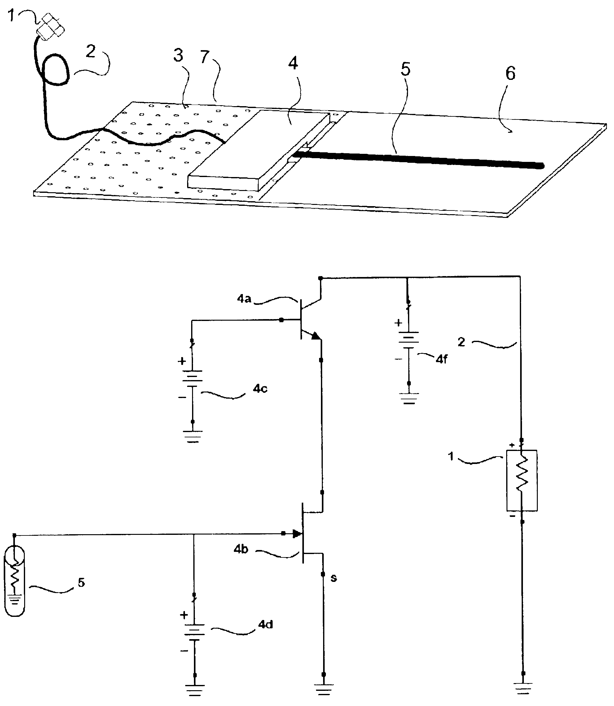
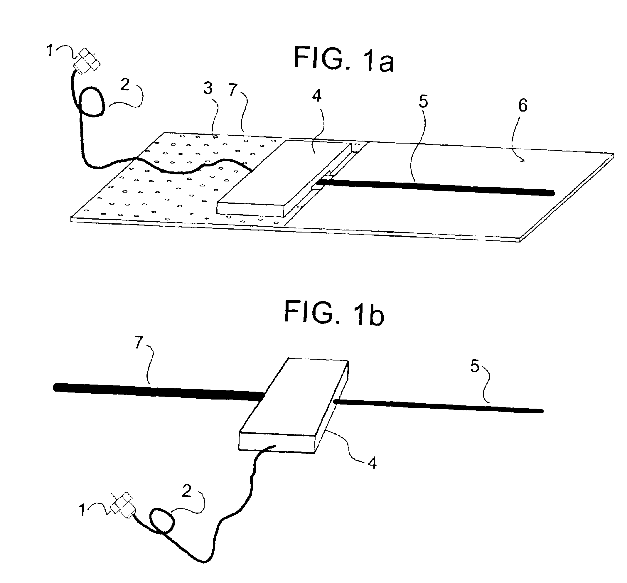
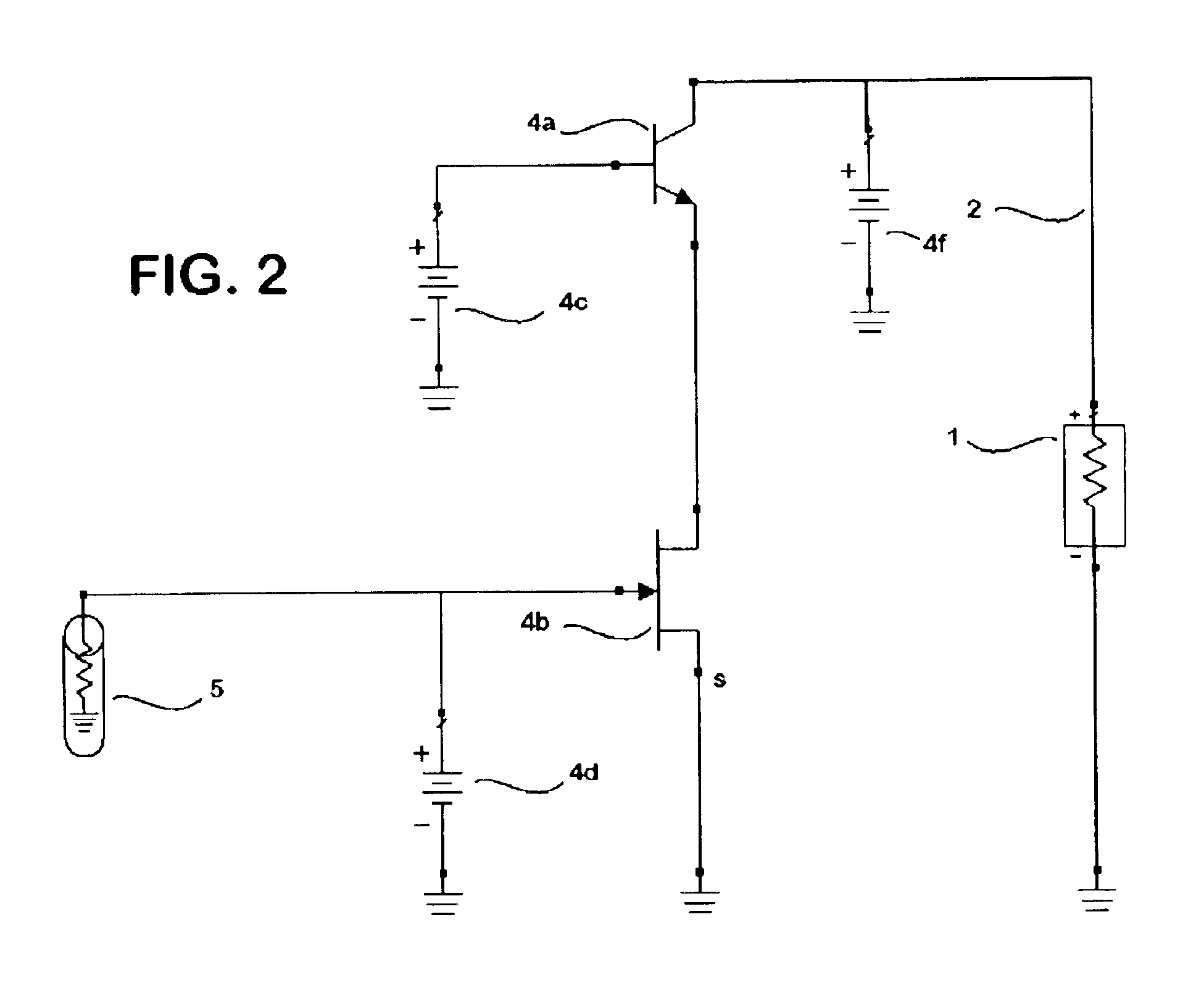
[0027]A preferred embodiment of the invention will be described within the context of a compact, inexpensive datacasting receiver, without limitation of the many other purposes and uses of antennas according to various embodiments of the present invention. It will be apparent to one of ordinary skill in the art that antennas and embodiments of the invention are also applicable to many other radio frequency reception applications; the actual source or nature of the signals and their use by some associated device is immaterial to the invention. Other end uses, for example, could include wireless networks such as IEEE 802.11 (b) WiFi, cellular telephony, satellite receivers, commercial broadcast, and automobile or other mobile application antennas for the reception of a wide range of broadcasts such as GPS navigation information, traffic conditions information, MP-3 music players with content supplied by broadcasters. Other applications could include MDS, broadband cellular / satellite c...


PUM


Abstract

According to some aspects of this invention, a compact, broadband active receiving antenna uses one or more high transconductance transistors such as Field Effect Transistor(s) paired with another Transistor and arranged in a Cascode amplifier configuration. Some embodiments involve a single high transconductance transistor arranged with a high efficiency transformer in a nondissipative feedback loop to improve linearity and dynamic range. The devices have a high input resistance, low input capacitance, low noise and a very high second and third order Intercept Point. Since the gain is primarily a function of the amplifying electronics, it is not necessary to increase the directivity of the antenna to achieve higher gain.

Description

RELATED APPLICATION[0001]This document relies on the priority of U.S. Ser. No. 60 / 351,476 filed Jan. 23, 2002 and entitled “Miniature Ultra-Wideband Active Receiving Antenna” which is incorporated herein by this reference.BACKGROUND[0002]This invention relates to radio frequency antennas, including various compact high performance active antennas designed to receive a broad spectrum of television, radio, or other like signals.[0003]The field of radio frequency receiving antennas for indoor applications is extensive and well understood within the constraints of traditional antenna designs. Passive antennas require that the receiving element bear some geometric relationship to the wavelength and propagation properties of the signal being received. They therefore need to be adjusted or otherwise modified when changing wavelengths. Similarly, traditional active receiving antennas rely on a good impedance match in order to efficiently couple received power to the receiver. Unfortunately,...

Claims


Application Information

Patent Timeline
Patent Type & Authority Patents(United States)
IPC IPC(8): H01Q23/00H04B1/18H04N5/44H04N5/64
CPCH01Q23/00H04B1/18H04N5/4401H04N5/64H04N21/414H04N21/426
Inventor ROWSER, ANDREWLONG, CHRISTOPHER DAVIDBORLAND, GLENN
Owner CALLAHAN CELLULAR L L C
Why Eureka
Try Eureka