Method and apparatus for clock timing recovery in χDSL particularly VDSL modems

a clock timing recovery and clock timing technology, applied in the field of digital data communication, can solve the problems of transmission medium interference with transmitted data, rate is still too low for many applications, and inability to meet the requirements of transmission data, etc., and achieves stable control voltage, reduce the cost of control circuitry, and accurate control

Inactive Publication Date: 2005-07-26
INFINEON TECH AG
View PDF9 Cites 49 Cited by
  • Summary
  • Abstract
  • Description
  • Claims
  • Application Information

AI Technical Summary

Benefits of technology

[0057]Using this a simple DAC together with the digital compensation circuitry simplifies and reduces

Problems solved by technology

This rate is unacceptable for many applications, e.g., picture transmission where pictures are constructed from large data files.
However, this rate is still too low for many applications.
Any transmission medium interferes with the transmitted data by adding noise, by attenuating its amplitude, and by changing its phase.
Digital modems suffer from these phenomena, reducing their ability to receive data without errors.
Errors are critical in digital modems.
However, it is not foreseen that in the near future the twisted pair copper lines between the telephone end users and the PABXs be replaced, due to their hugh number, and to the complexity of replacing them.
In leased lines, a wider bandwidth is available, however the possible data rate is still limited by the fact that long lines introduce very large attenuation, especially in the higher range of the bandwidth, which exceeds 8 MHz in VDSL modem transmission.
Moreover, telephone lines pass through switching exchanges conducted by the local telephone companies, and this may be a very noisy environment which disrupts the transmitted data.
This long duration of the impulse response of the line leads to a severe Inter symbol Interference (ISI) which may result in a large errors at the receiving modem if cannot canceled, and practically

Method used


Image

  • Method and apparatus for clock timing recovery in χDSL particularly VDSL modems
  • Method and apparatus for clock timing recovery in χDSL particularly VDSL modems
  • Method and apparatus for clock timing recovery in χDSL particularly VDSL modems

Examples


Embodiment Construction

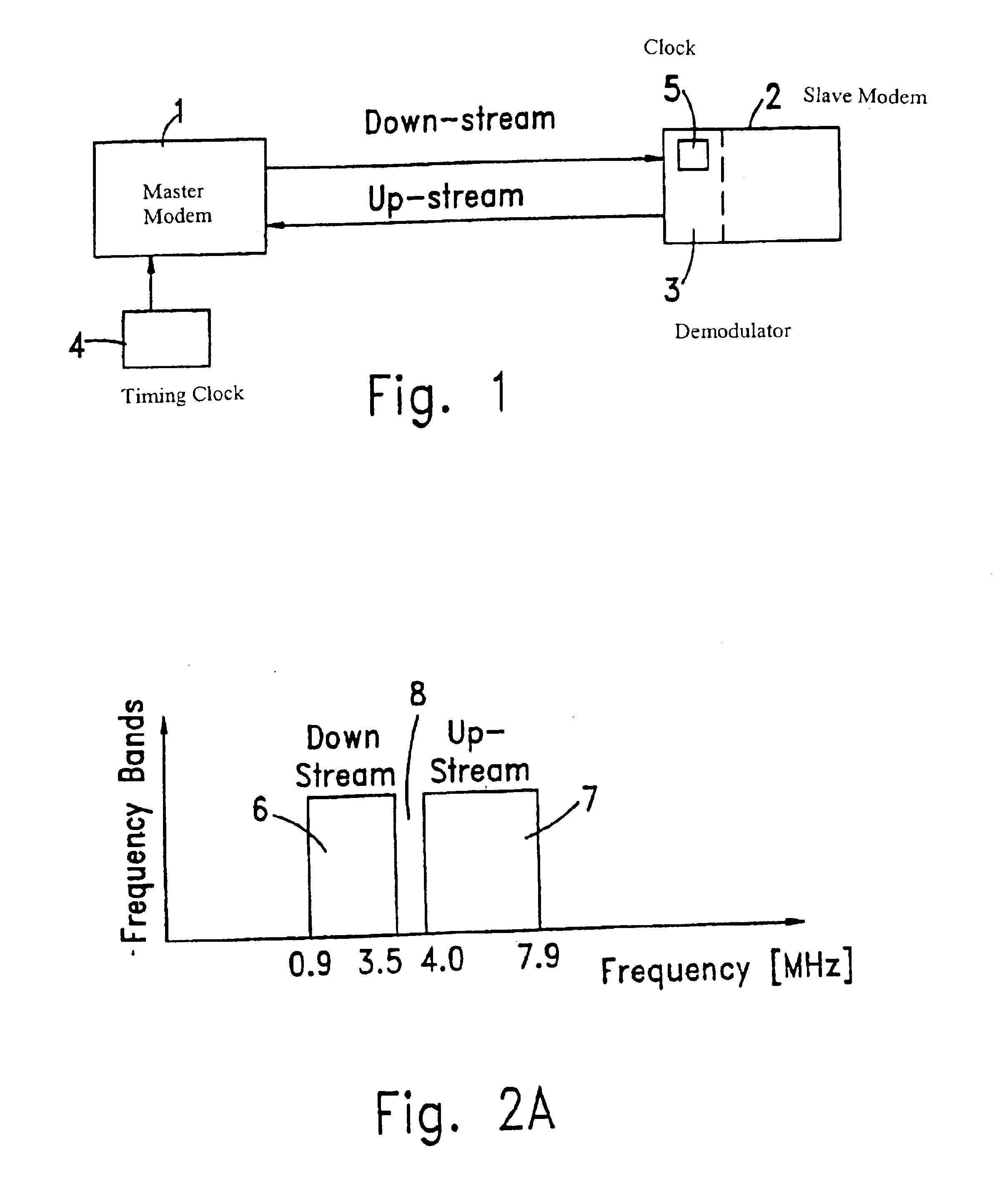
[0069]FIG. 1 illustrates a full duplex data communication channel between master and slave χDSL modems, using standard telephone line made from copper wires pair. A timing clock 4, which may be supplied by the local telephone system or by a Synchronous Digital Hierarchy (SDH) system, drives the master modem to transmit data (symbols) downstream to the slave modem 2. The slave modem is driven by another clock 5, which is a part of the slave's demodulator 3. Clock 5 should be synchronized to clock 4 since the clock defines the difference between symbols. After synchronization, clock 5 times the downstream symbol reception and upstream symbol transmission to the master modem.

[0070]The frequency spectrum of an χDSL channel utilizes two separated frequency bands using Frequency Division Duplex (FDD) as shown in FIG. 2A. The first band 6 occupies the range from 0.9 MHz to 3.5 MHz and is used for down-stream transmission, whereas the second band 7, occupies the range from 4 to 7.9 MHz and ...


PUM


Abstract

Method and modem for fast timing recovery of transmitted data between a master χDSL modem and a slave χDSL modem, over a noisy, high loss, high distortion wiring. Transmitted QAM symbols are received and sampled at the slave modem. The sampled data is split into in-phase and quadrature channel, each of which is filtered by matched filter. The filtered outputs are sampled at twice the symbol rate and the lower and upper band edge components are extracted by modulating each of the sampled sequences of outputs with two discrete time sequences: cos(0.5 π n)=. . . 1,0,−1,0 . . . and sin(0.5 π n)=. . . 0,1,0,−1 . . . . Each of the resulting products is filtered with a first order low-pass filters and re-sampled again at the symbol rate. The Bit Error Rate is computed, and the slave modem switches from blind timing recovery mode, to data directed timing recovery mode, after the Bit Error Rate has sufficiently decreased.

Description

FIELD OF THE INVENTION[0001]The present invention relates to digital data communication between two locations over the connecting wiring. More particularly, the invention relates to the use of Very High speed Digital Subscriber Loop (VDSL) modems for transferring data at high rates between two locations connected at least partially by conventional, twisted copper wires.BACKGROUND OF THE INVENTION[0002]The art has devoted considerable attention to the problem of transmitting data in a high rate between users being at different locations. Such users, may be home Personal Computers (PCs), office desktop workstations, cable television broadcasting services, Local Area Networks (LANs) and others. In some applications users are connected to each other by modems (modulator-demodulator) which encode the digital data to be delivered from one point (user) to another point and transmit the encoded data through a data link which may be, for instance, an analog communication channel. Such data c...

Claims


Application Information

Patent Timeline
IPC IPC(8): H04L27/38H04L7/027H03M1/66
CPCH03M1/66H04L7/027H04L27/38H04L7/00
Inventor PORAT, BOAZHARPAK, AMNONPELEG, SHIMON
Owner INFINEON TECH AG
Why Eureka
Try Eureka