
Method of manufacturing a catalytic converter

a manufacturing method and catalytic converter technology, applied in the direction of catalyst activation/preparation, metal/metal-oxide/metal-hydroxide catalysts, machines/engines, etc., can solve the problems of extraordinarily high particulate oxidation rate and complete clogging of substrates, so as to reduce the center channeling and maximize the utilization of the entire matrix , the effect of increasing the residence time of particulates

Inactive Publication Date: 2005-08-02
ESW TECH
View PDF14 Cites 16 Cited by
  • Summary
  • Abstract
  • Description
  • Claims
  • Application Information

AI Technical Summary

Benefits of technology

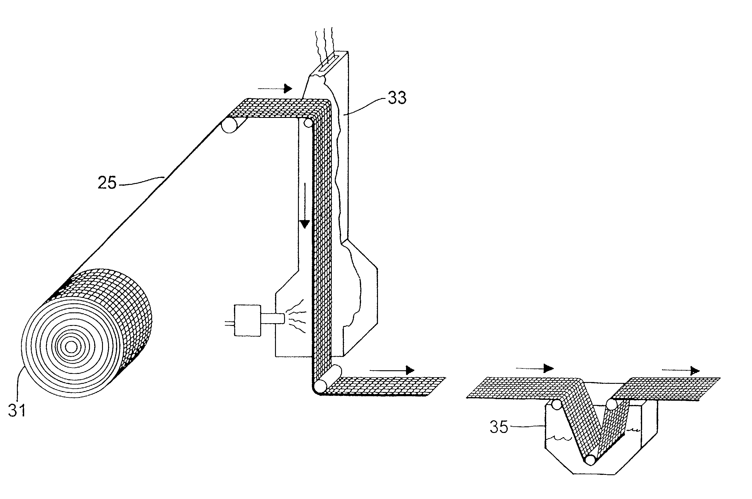
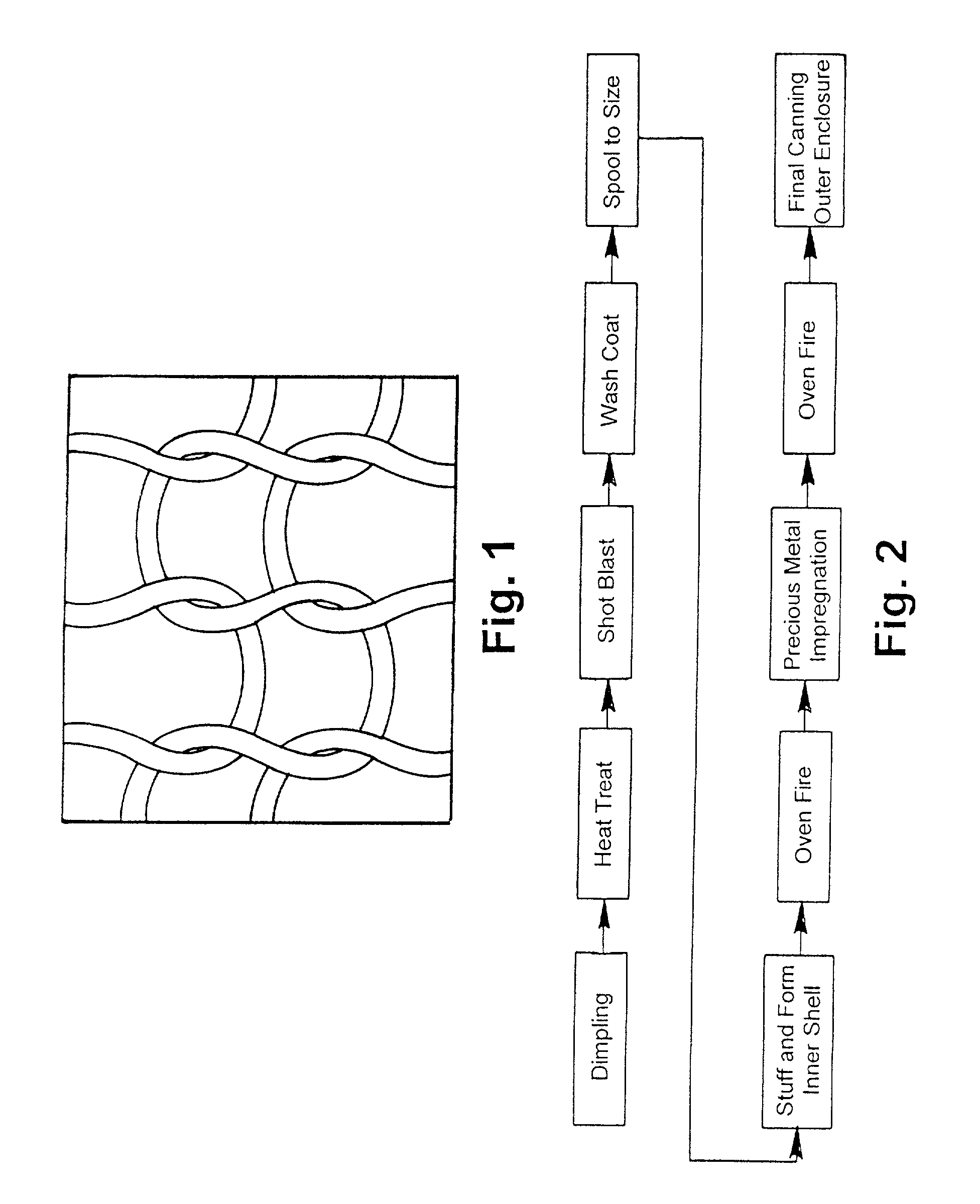
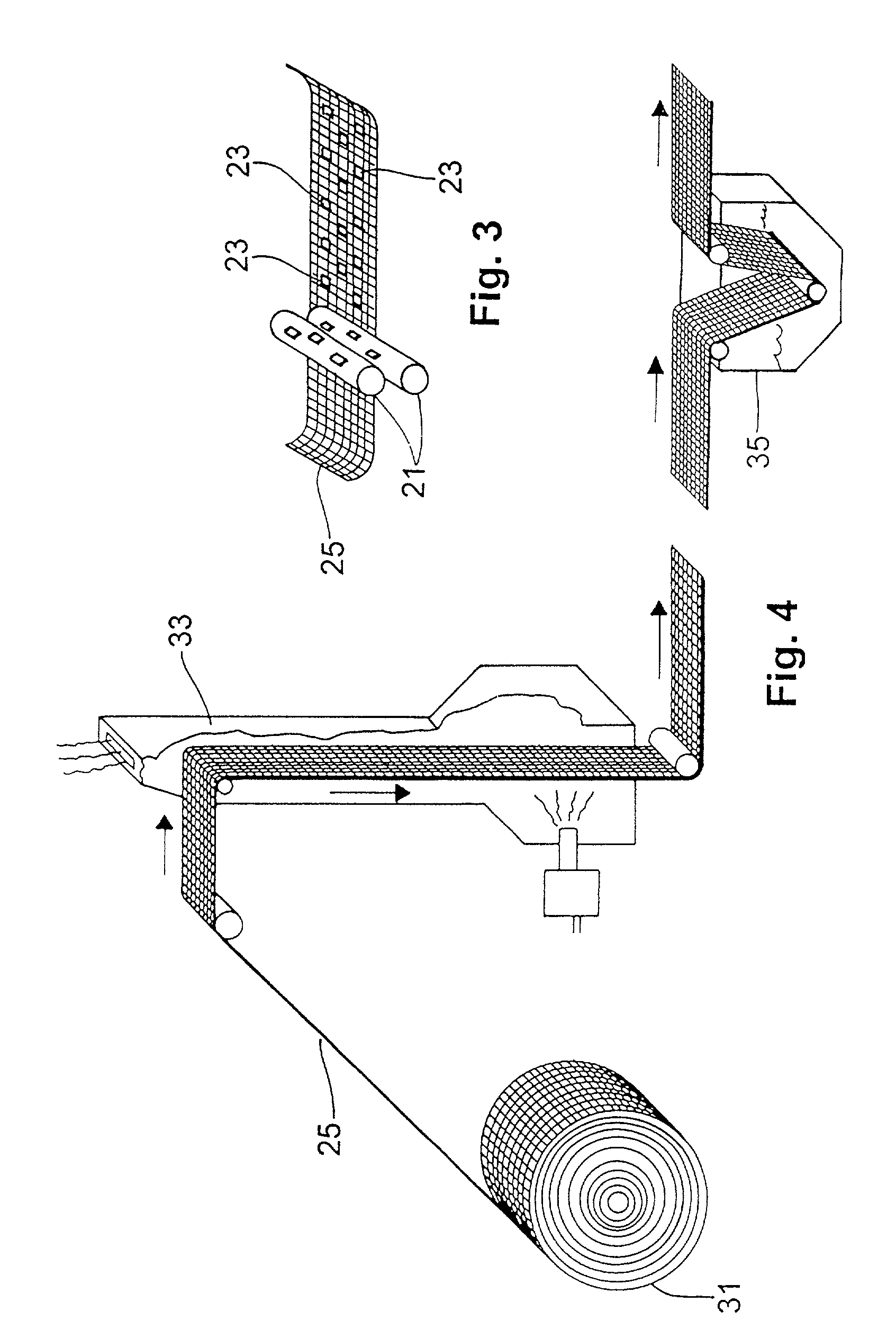
[0036]The manufacturing steps include first roll-stamping small, raised dimples in the fabric substrate to control its density. The dimples standoff adjacent layers in the spooled roll, creating greater space between them. Next, the dimpled fabric undergoes high temperature firing for hardening and degreasing, and then water quenching to harden the metal which improves heat tolerance. The treated metal knit is then aluminum oxide shot-blasted to etch the fabric surface for improved ceramic coating adhesion and increase surface area. Next, the fabric is coated with a wet slurry of an undercoating (“wash coat”) prior to spooling and pressing the fabric into individualized cartridges that are held tightly wound by an encircling sleeve. Next, the sleeved spools are oven-fired. Then, the fired spools are impregnated with the catalytic precious metal. The impregnated sheathed spools are then oven-fired again and finally “canned” into an outer enclosure.
[0038]The operation of the catalytic reactor of the present invention may be briefly described as follows. As fast moving exhaust gas encounters the face of the reactor cartridge, the cartridge design disperses exhaust gas evenly throughout the volume of the matrix, thus eliminating center channeling and utilizing the entire matrix more efficiently. Exhaust gas then encounters a torturous flow path consisting of a knitted metal fabric matrix having approximately 27 million uniform loophole paths per cubic foot of spooled metal fabric volume. This unique medium makes it impossible for carbon particles to pass through the device without having relentlessly impacted the catalyzed threads making up each loophole path. Carbon particles incinerate as they impact the fabric threads which are glowing red from the catalytic exothermic reaction. The reactor design slows down the unburned carbon particles rate of passage, yet the loophole density is sufficiently open as to eventually let unburned particles pass. The center-to-center loophole density is sufficiently dense as to allow radiant heat from each thread to combine and cause temperatures in the airspace between them to maintain sufficient temperature to incinerate passing carbon particles. This structure causes gas turbulence and increased particulate residence time within this unique oxidizing environment and results in extraordinarily high particulate oxidation rates.
[0039]Because the exhaust is able to move in all directions inside the reactor, it tends to evenly disperse immediately upon entering the face. This effect eliminates honeycomb substrate “channeling” and makes the full volume of reactor substrate available regardless of exhaust velocity and volume. Furthermore, since the carbon burns in the process, additional heat is liberated. Micron-sized particles passing between the fabric's loops are incinerated in the high temperature field, and also as they impact the fabric. As a result, mid-cartridge temperatures are maintained 200–300 degrees Fahrenheit higher than mid catalyst temperatures noted with conventional oxidation catalysts under the same conditions, of the same volume and catalytic loading. Higher mid-reactor temperatures are desired because the reactor is incinerating carbon in addition to oxidizing gaseous pollutants. Conventional oxidation catalysts are only designed to oxidize gaseous unburned hydrocarbon and other gaseous organic materials by way of exothermic reaction on the treated honeycomb surface. Other objects and advantages of the present invention will be readily apparent to those with skill in the art from the following drawings and description of the preferred embodiment.

Problems solved by technology

Regardless of insertion pressure or viscosity of the slurry, the enormous surface area and surface tension tends to cause the coating materials to conglomerate and completely clog the substrate.
This structure causes gas turbulence and increased particulate residence time within this unique oxidizing environment and results in extraordinarily high particulate oxidation rates.

Method used


Image

  • Method of manufacturing a catalytic converter
  • Method of manufacturing a catalytic converter
  • Method of manufacturing a catalytic converter

Examples


Embodiment Construction

[0049]Referring now to FIG. 1, a critical element of the present invention is the core substrate. As shown in this Figure, the substrate is made from a knitted metallic fabric which itself has an organized and repeatable pattern. The fabric has an open loop structure such that exhaust gas easily passes through it and may be a single or double-strand knit. The fabric is made of alloy wire threads which are knitted into a metal fabric that has a consistent pattern with uniform density and convenient widths such as 2″, 4″ and 6″ that can be of any length convenient for mass production, for example, 100 to 200 feet. The long rolls of fabric are then processed in a continuous manner to produce small substrate spools. The catalyzed metal fabric can be of any width or any desired knit density. The spooled reactor cartridge has 27 million loophole paths per cubic foot of volume however different knit densities may be employed as desired. The finished substrate unit provides a highly efficie...


PUM

PropertyMeasurementUnit
Angleaaaaaaaaaa
Temperatureaaaaaaaaaa
Lengthaaaaaaaaaa

Abstract

A manufacturing process for producing a particulate reactor substrate according to the invention includes the steps of first roll-stamping small, raised dimples into the fabric substrate to control its coiled density. The dimpled fabric then undergoes high temperature firing for hardening and degreasing, and then water quenching to harden the metal which improves heat tolerance. The treated metal weave is then aluminum oxide shot-blasted to etch the fabric surface for improved ceramic coating adhesion and to increase surface area. Next, the fabric is coated with a wet slurry of an undercoating (“wash coat”) prior to spooling and pressing the fabric into individualized cartridges that are held tightly wound by an encircling sleeve. Next, the sleeved spools are oven-fired and then the fired spools are impregnated with the catalytic precious metal. The impregnated sheathed spools are finally oven-fired again and “canned” into an outer enclosure.

Description

FIELD OF THE INVENTION[0001]This invention relates to catalytic converters and particulate control devices for the exhaust of internal combustion engines. More specifically, this invention pertains to a carbon particulate oxidizer device which is intended for use with diesel engine exhaust. This invention also pertains to a process of manufacturing the oxidizer's unique catalytic element.BACKGROUND OF THE INVENTION AND PRIOR ART[0002]Recent, more stringent government regulation of diesel engine tailpipe emissions, have prompted development and application of various means to reduce these emissions. New diesel engine exhaust emissions regulations are focused on reducing diesel engine carbon particulate matter emissions (black soot). Of greatest concern are micron-sized carbon char particles, other particulate matter, and organic compounds which are adsorbed onto the surface of the carbon. A body of clear evidence now exists which links diesel particulate matter to a variety of seriou...

Claims


Application Information

Patent Timeline
IPC IPC(8): B21D35/00B01D53/94B01J23/40B01J35/06B01J37/02F01N3/022
CPCB01D53/9454B01J23/40B01J35/06B01J37/0225B21D35/00F01N3/022Y10T29/49879B01D2255/9202B01D2258/012B01J37/0242F01N2330/12F01N2330/18Y02T10/20Y02T10/22Y10T29/49345Y10T29/49982Y10T29/49885B01D2255/102Y02T10/12B01J35/58
Inventor MARINO, JR., ROBERT J.
Owner ESW TECH
Learn More