Massage treatments given by hand can be costly for the patient and tiring for the masseuse.
In addition, manual manipulations are not typically capable of sustained
massage of deep subdermal tissue
layers.
Using a roller as a lifting or petrissage element in a
body contouring or massage device as disclosed in some of the prior art above can be disadvantageous in that use of rollers increases the manufacturing cost of the device and complicates
assembly of the device.
Cost and complexity of manufacturing are especially increased for devices employing rollers which are motorized or otherwise mechanically activated.
Similarly, maintenance and repair of devices with rollers can increase the overall cost to the purchaser.
Moreover, motorized and mechanized roller devices can be difficult to clean and may require partial disassembly to clean.
Some rollers also limit the direction and movement of the device along the
skin of the patient, restricting movement of the device to substantially forward and backward movements.
In this way, roller devices limit the types of treatments that can be offered using the device and may prove difficult to use.
It has been found that there is discomfort related to prior art designs of massage and
body contouring devices.
As the roller moves along the surface of the
skin, the skin can be drawn up along the roller and get caught in the space between the roller and the housing of the device.
Where the lifting action of the skin is increased by motorized or mechanically activated rollers or by a vacuum source, the patient's discomfort from pinching may increase.
The design of the housing of the device may increase a patient's chances of uncomfortable contact with sharp edges or corners of the housing, such as with a square or angular shaped device.
In devices using vacuum suction to lift the skin, if the portion of the device which contacts the patient's skin to create the vacuum seal has sharp edges, the vacuum suction may cause the skin to be pinched along the area of the seal.
This is particularly the case when the vacuum suction becomes too strong, and there is no safety release valve to reduce the suction.
A patient's skin may also be irritated by the device where the device comes into direct contact with the skin.
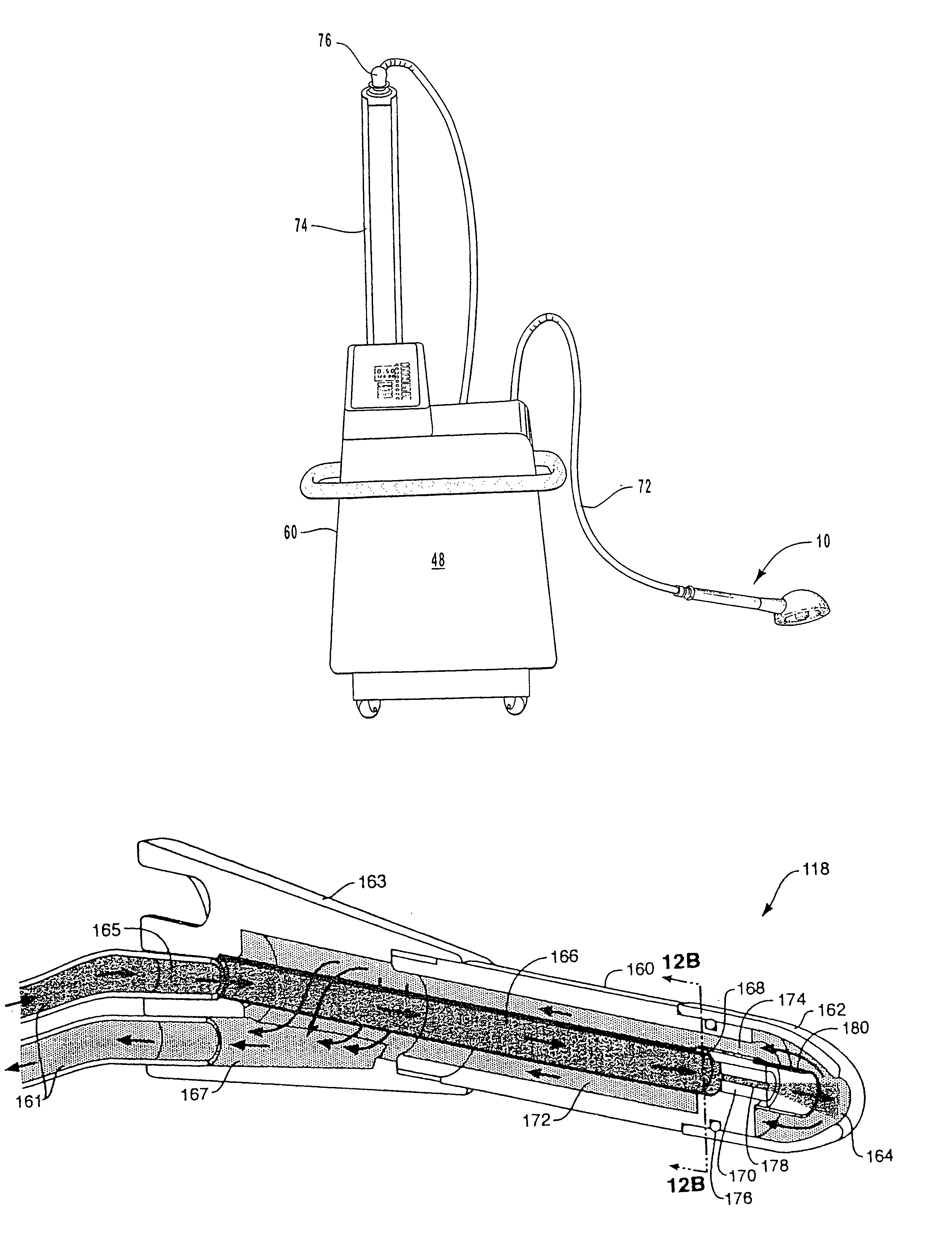
Each stage of operation within current
dermabrasion systems suffer problems that prevent optimal and efficient operation on a subject or patient.
One problem is the handling of the
abrasive material at the supply point.
These containers are usually difficult to access and lead to waste and unnecessary
exposure to the abrasive material during filling.
Further, due to the dynamics of the content level changing, the systems fail to deliver consistent amounts of abrasive material from the supply containers to the hand piece.
As such, the results of the abrasive operation are inconsistent and vary in the length of time normally needed to perform a typical procedure / session.
As the container goes from full to empty, performance can suffer severely, with as much as a 75 percent reduction in abrasive concentration in the air
stream.
Additionally, few, if any, systems are able to utilize all the contents of the supply container before needing refilling.
An additional problem with current supply containers is that they draw upon
ambient air.
This is especially a problem in that most systems utilize a small output aperture that clogs easily, particularly when the abrasive material becomes damp with
humidity, leading to clumping and clogging and generally inconsistent delivery of abrasive.
Some systems utilize an electronic control that causes pulses resulting in pressure surges and non-uniform delivery of the abrasive.
Other systems utilize control systems that are difficult to adjust, hard to reset and fail to provide repeatable consistent results for subsequent treatments.
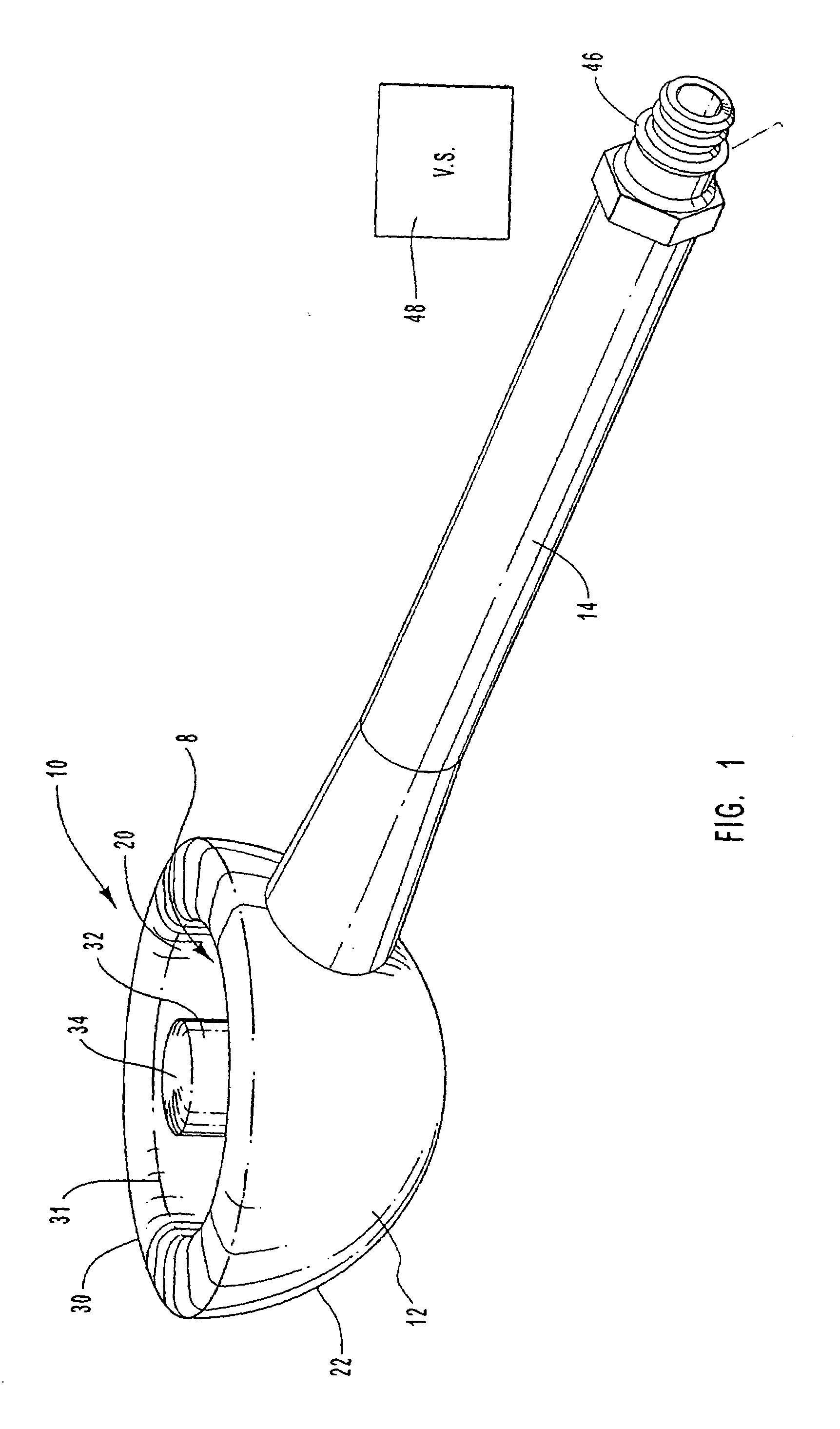
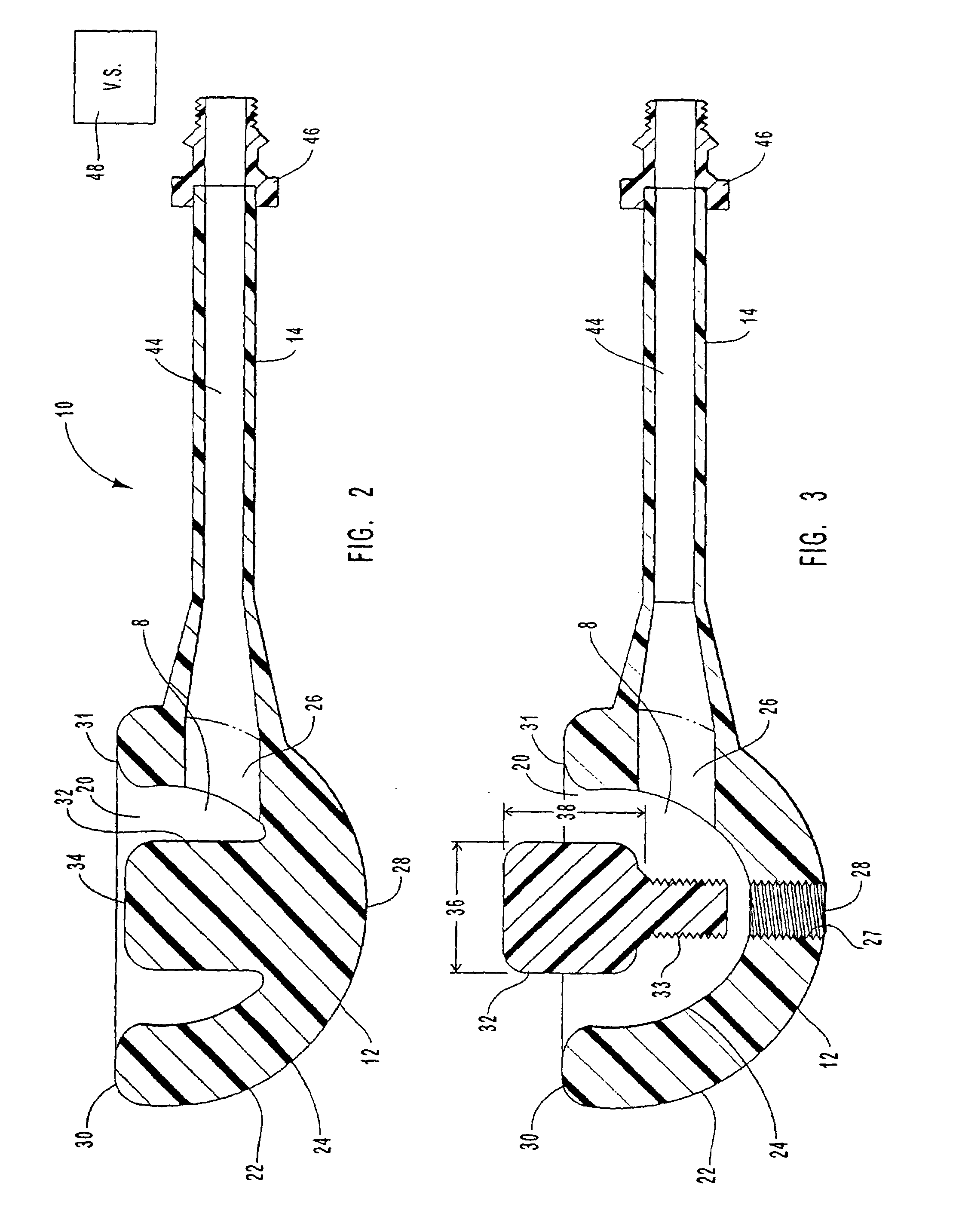
Hand pieces suffer several problems.
One problem is that the apertures tend to
restrict the flow of the abrasive material to the skin as well as hinder removal of the abraded material and the abrasive during the abrasion procedure.
Further, the dermabrasion procedure involves removal of skin and sometimes blood, so there is concern that the use of the same wand from patient to patient is unsanitary and unhealthy.
Attempts to make the hand piece more hygienic by having disposable and replaceable wand tips has been unsuccessful as the tips merely prevent
contamination at the aperture level without addressing a problem known as back
contamination, which occurs when refuse debris within the wand from a previous procedure contaminates the wand tip in
spite of the replacement of a fresh tip.
As such, these pieces are difficult to clean and therefore, undesirable for long term use.
Also, most hand pieces are expensive to manufacture.
They can be heavy and awkward to use, such that the
technician suffers discomfort and fatigue during long sessions or over several sessions during the same day.
Since the piece needs to be small enough to
handle, they often have restricted flow paths that detrimentally affect flow rate and delivery of the abrasive for optimal results and for quick pick up of the waste debris.
Most systems are permanently mounted and are difficult to access, empty, and clean.
Failure to clean the container can result in unwanted growths and other hazardous health risks that should be avoided at all times.
The waste accumulation systems often have small exhaust apertures that can easily clog with waste products resulting in restricted air flow within the overall system.
Such filters are a major source of clogging and reduction of optimal air flow within the entire system, thereby leading to poor dermabrasion results since less abrasive material is being carried within the system at a reduced speed.
Similar to the supply system, one solution has been to use
back pressure to clear and clean the filters or unplug the clogs in the waste accumulation system, but this adds cost and complexity to the overall design, which can result in
mechanical failure, decreased abrasion performance, and increased costs of production and operation.

