High efficiency conversion of nitrogen oxides in an exhaust aftertreatment device at low temperature

a nitrogen oxide and aftertreatment device technology, applied in the direction of machines/engines, electric control, instruments, etc., can solve the problems of nox conversion being too low and the reducer supplied to the catalyst slips, and achieve the effect of less reductant, less reductant, and high conversion efficiency

Inactive Publication Date: 2005-08-09
FORD GLOBAL TECH LLC
View PDF31 Cites 29 Cited by
  • Summary
  • Abstract
  • Description
  • Claims
  • Application Information

AI Technical Summary

Benefits of technology

[0005]A primary advantage of the present invention is that a lean NOx catalyst processing lean exhaust gases operates with substantially higher conversion efficiency in a lower temperature range than heretofore possible. Disadvantages of prior art approaches are overcome by a method for supplying reductant to a catalyst receiving exhaust gases from an internal combustion engine in which a quantity of reductant stored within the catalyst is determined. While said quantity is less than a predetermined quantity, reductant is supplied to the catalyst under predetermined conditions. The predetermined conditions may be a temperature in the catalyst greater than 300° C. or a NOx concentration in the exhaust gases being less than 25 ppm.
[0006]The inventors of the present invention have recognized that it is unnecessary to supply reductant continuously. After storing reductant under prescribed conditions, reductant delivery can be lessened or discontinued. An additional advantage of the present invention is that significantly less reductant is supplied to the catalyst than prior art methods in which reductant is supplied continuously to the catalyst.
[0007]Another advantage of the invention herein, over prior art, is that because less reductant is supplied to the catalyst, less reductant slips through the catalyst into the tailpipe.

Problems solved by technology

The problems with prior art methods are that some of the reductant supplied to the catalyst slips through the catalyst unreacted and NOx conversion is too low at temperatures below about 250° C.

Method used


Image

  • High efficiency conversion of nitrogen oxides in an exhaust aftertreatment device at low temperature
  • High efficiency conversion of nitrogen oxides in an exhaust aftertreatment device at low temperature
  • High efficiency conversion of nitrogen oxides in an exhaust aftertreatment device at low temperature

Examples


Embodiment Construction

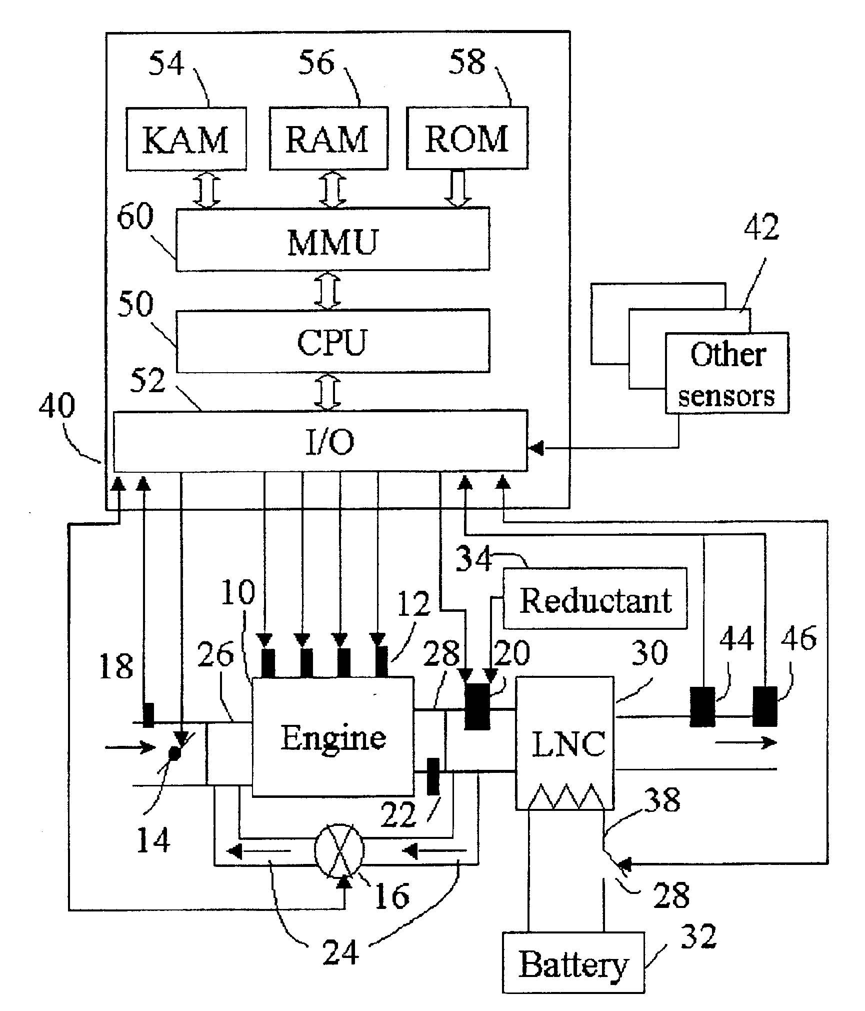
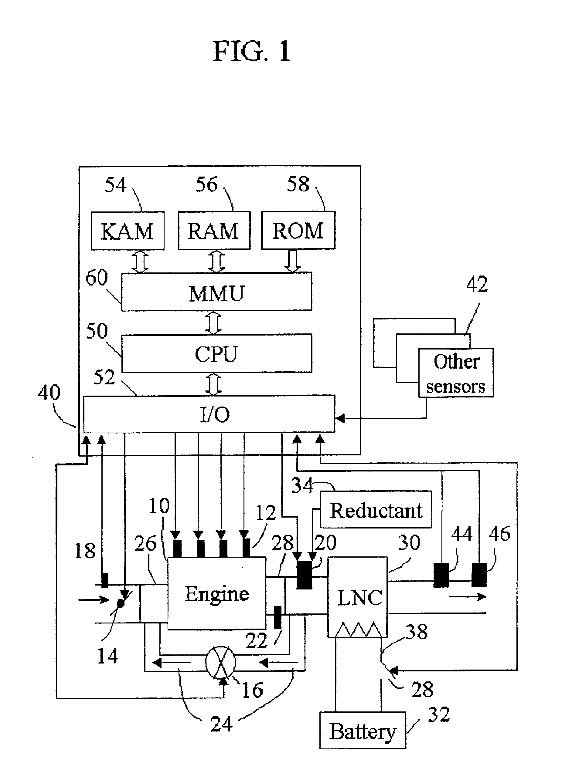
[0018]In FIG. 1, an internal combustion engine 10 is supplied air through an intake line in which a throttle valve 14 may be disposed. Position of throttle valve 14 may be controlled by an electronic control unit (ECU) 40. A mass airflow sensor 18 may be placed in the intake line, supplying a signal to ECU 40 indicative of intake airflow into engine 10. Alternatively, a speed density system may be used to infer intake airflow. Speed density relies on a sensor in the intake system providing an indication of pressure in the intake manifold and an engine speed sensor, shown as other sensors 42. Engine 10 is supplied fuel by injectors 12 (fuel supply to injectors 12 not shown). Fuel injection timing and duration may be controlled by mechanical means. More commonly, however, the fuel injection system is of a type, eg., common rail design, which allows timing and duration to be controlled by ECU 40. Engine 10 may be equipped with an exhaust gas recirculation (EGR) system, which connects e...


PUM


Abstract

A system and method for delivering reductant to a lean NOx catalyst receiving exhaust gases from an internal combustion engine operating at a lean air-fuel ratio in disclosed. Reductant supply is based on an amount of reductant stored within the catalyst. Furthermore, reductant is supplied under prescribed conditions including an exhaust gas concentration upstream of the catalyst of less than 25 ppm NOx or the catalyst at a temperature greater than 300° C.

Description

BACKGROUND OF INVENTION[0001]The present invention relates to a system and a method for improving conversion efficiency of a lean NOx catalyst in a diesel or lean burn gasoline engine, and, more particularly, to improving conversion efficiency by controlling delivery of a NOx reductant.[0002]Internal combustion engines commonly rely on exhaust aftertreatment devices to convert regulated components: carbon monoxide, hydrocarbons, and nitrogen oxides (NOx), into carbon dioxide, water, nitrogen, and oxygen. Exhaust catalysts have been extensively developed to obtain high conversion efficiencies on stoichiometric exhaust gases. Stoichiometric conditions are achieved when the fuel and oxidizer supplied to the engine is in a proportion which, if reaction of the fuel were complete, produce carbon dioxide, water, and nitrogen. It is known to those skilled in the art, though, that higher fuel efficiency is obtained from engines operating at air-fuel ratios lean of stoichiometric, that is, wi...

Claims


Application Information

Patent Timeline
Patent Type & Authority Patents(United States)
IPC IPC(8): F01N3/20F02D41/14F02D41/02F02M25/07F01N3/08F02D43/00F01N3/24F01N3/36F02D45/00
CPCF01N3/2013F01N3/208F02D41/0275F02D41/1459F02D41/146F01N2370/04F01N2550/02F01N2560/021F01N2570/18F01N2610/02F01N2610/03F02D41/005F02D41/1441F02D41/187F02D2041/1468F02M25/0756Y02T10/26Y02T10/24F02M26/48Y02T10/12
Inventor XU, LIFENGMCCABE, ROBERT WALTER
Owner FORD GLOBAL TECH LLC
Why Eureka
Try Eureka