Device for measuring aberration refraction of the eye

a technology of aberration and measuring devices, applied in the field of medical ophthalmological equipment, can solve the problems of increasing aberration measurement errors, low accuracy and productivity, and the fixed field of view of raster photoelectric analyzers of measuring devices with hartmann-shack sensors, so as to improve accuracy

Inactive Publication Date: 2005-08-23
TRACEY TECH
View PDF28 Cites 46 Cited by
  • Summary
  • Abstract
  • Description
  • Claims
  • Application Information

AI Technical Summary

Benefits of technology

[0027]To align the instrument relative to the patients eye as well as to enhance accuracy and enable automation of the aligning process, the instrument is provided with a third beam splitter to insert a channel for eye alignment verification of the instrument and the patient's eye. In a preferred embodiment, the co-axial verification channel comprises one or more point of light sources and a TV or electro-optic detecting device, together serving to display the pupil and/or eye image and providing a permission channel to measure eye characteristics when the optical axis of the instrument and the visual axis of the patient's eye coincide. To enable the instrument to be used without dilating the pupil with a medicine, a laser radiation source and/or infrared light sources are incorporated into the coaxial verification alignment mechanism. It is contemplated that the instrument can be used to make refraction measurements under conditions simulating either day or night light conditions.
[0028]In an alternate

Problems solved by technology

Major disadvantages of the above measuring devices are their low accuracy and productivity, a prolonged measurement process resulting in the patient's fatigue, variations in accommodation, and eye movements while taking measurements, thereby increasing the aberration measurement errors.
A common disadvantage of the measuring devices with a Hartmann-Shack sensor is the fixed field of view of the raster photoelectric analyzer of transverse aberrations due to the mechanically rigid construction of the lens raster and the invariable mutual spatial arrangement of the photosensitive elements of the charged coupled device or CCD camera.
This results in a fixed configuration of grid sites at the pupil plane in which aberrations are measured, with no flexibility of reconfiguring these grid sites for more detailed measurements in separate zones of the pupil depending on their aberration properties.
Other disadvantages of existing devices include: they do not incorporate means for providing an accurate reproducible “linkage” of the patient's eye to the spatial co-ordinates of the measuring device; they do not incorporate a means for adjusting the accommodation of the patient's eye that is necessary for studying the dependence of aberrations on the accommodation characteristics; they are not capable of taking measurements on a dilated pupil without using medicines.
The spatially resolved objective autorefractometer disclosed in U.S. Pat. No. 5,258,791 preferably using laser ray tracing, has a number of substantial problems relating to performance in the following basic and auxiliary functions: preliminary alignment of the optical axis of the device relative to the visual axis of the eye; accommodation monitoring of the patient's eye; allocation of points within the pupil at which refraction is measured; and measurement of the angle of laser beam incidence into the patent's eye.
Preliminary alignment of the optical axis of prior art devices relative to the visual axis of the eye may be problematic for at least the following reasons: first, the visual axis of the eye is assumed to be the line passing through the geometric center of the pupil and the fovea.
In addition, the pupil may not be symmetrical.
Second, in prior art devices in

Method used


Image

  • Device for measuring aberration refraction of the eye
  • Device for measuring aberration refraction of the eye
  • Device for measuring aberration refraction of the eye

Examples


Embodiment Construction

[0037]While the making and using of various embodiments and methods of the present invention are discussed in detail below, it should be appreciated that the present invention provides many applicable inventive concepts, which may be employed in a variety of specific contexts. The specific embodiments discussed herein are merely illustrative of specific ways to make and use the invention and do not delimit the scope of the invention.

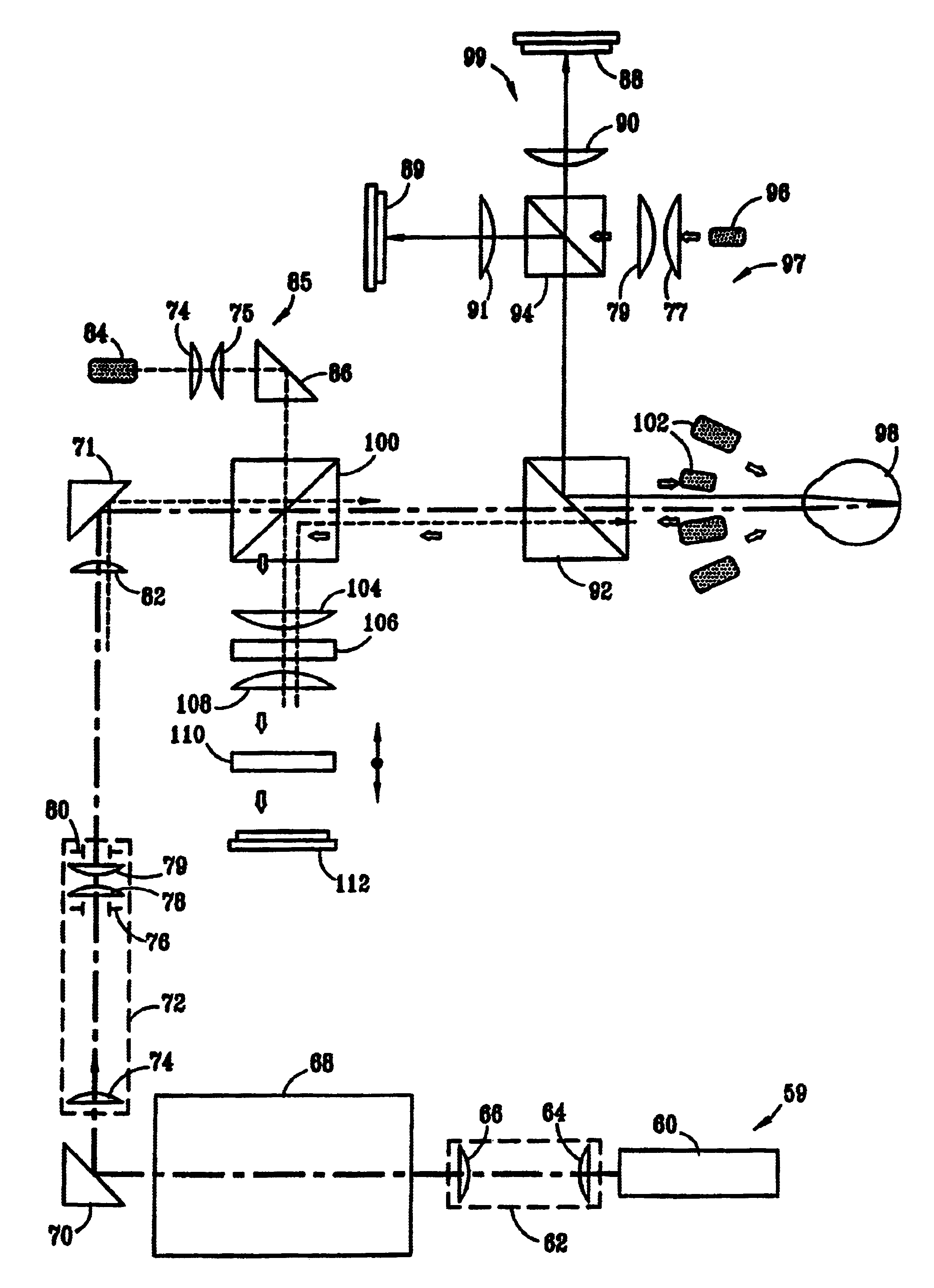
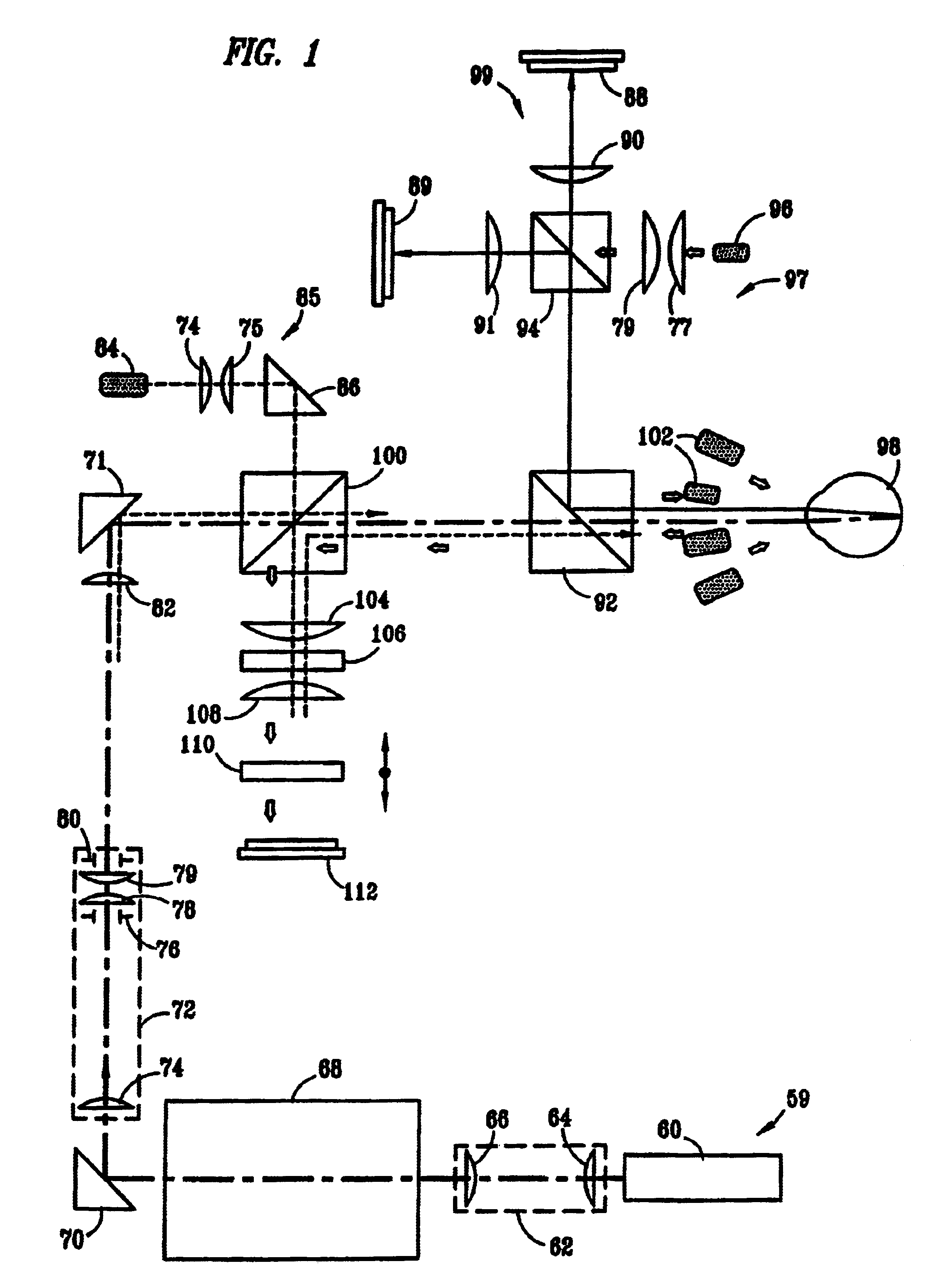
[0038]FIG. 1 schematically depicts the optical channels of one embodiment of the total aberration portion of the refractometer of the subject invention. A spatially defined parallel beam input channel 59 extends from a light source such as a laser or other low diffusion light source up to the eye of a patient 98. In one preferred embodiment a 650λ laser was employed. Along the spatially-defined parallel beam input channel is a cylindrical telescope 62 including two lenses 64 and 66. Light from the cylindrical telescope enters the deflector 68. The deflec...


PUM


Abstract

An instrument for measuring aberration refraction of an eye is provided, having: a lens system defining an instrument optical axis and an alignment device for aligning the visual axis of the eye with the instrument optical axis. A light source (1) produces a probing beam that is projected through the lens system parallel to the instrument optical axis and is selectably positionable partially off-set from the instrument optical axis for entering the eye (15) parallel to the instrument optical axis at a plurality of locations on the cornea of the eye. A photodetector (19) measures the position of probing beam light scattered back from the retina of the eye to measure aberration refraction of the eye at a plurality of locations.

Description

CROSS REFERENCE TO RELATED APPLICATIONS[0001]This is a continuation of U.S. Application Ser. No. 09 / 634,487, filed Aug. 8, 2000 now U.S. Pat. No. 6,409,345, which is a continuation-in-part of PCT Application No. PCT / US99 / 23327, filed Oct. 7, 1999 in which the U.S. is a designated country and which claims the priority of Ukrainian Patent Application No.: 98105286, priority filing date Oct. 7, 1998, all of which are claimed for priority in the present application.TECHNICAL FIELD OF THE INVENTION[0002]The present invention relates to medical ophthalmological equipment, more specifically, it relates to devices for measuring the refraction of the eye as a function of spatial pupil coordinates.BACKGROUND OF THE INVENTION[0003]Measuring devices are known, for the study of the refraction component of the optical system of the eye, which depend on spatial pupil coordinates. These include M. S. Smirnov's device for measuring the wave aberration [1], Van den Brink's device for measuring the tr...

Claims


Application Information

Patent Timeline
IPC IPC(8): A61B3/107A61B3/103A61B3/10
CPCA61B3/1015A61B3/107A61B3/0066A61B3/10
Inventor MOLEBNY, VASYL V.PALLIKARIS, IOANNISCHYZH, IGORSOKURENKO, VYACHESLAVNAOUMIDIS, LEONIDASWAKIL, YOUSSEF
Owner TRACEY TECH
Why Eureka
Try Eureka