Semiconductor connection substrate

a technology of semiconductors and substrates, applied in the field of semiconductor parts, can solve the problems of large variation in the warp and size of wiring materials, inability to form microscopic wirings and through holes of the order of m by photolithography, and achieve the effect of desirable manufacturing yield

Inactive Publication Date: 2005-08-23
RENESAS ELECTRONICS CORP
View PDF11 Cites 25 Cited by
  • Summary
  • Abstract
  • Description
  • Claims
  • Application Information

AI Technical Summary

Benefits of technology

[0017]This and other objects of the invention are achieved by a semiconductor connection substrate which connects a semiconductor element to a mounting substrate, such as a printed substrate. The semiconductor connection substrate comprises an insulator substrate; a plurality of electrodes having different areas provided on the insulator substrate; one or more elements selected from a capacitor element of dielectric material sandwiched between the electrodes, an inductor element and resistor element; a metal wiring connecting the elements; a metal terminal part of the metal wiring; and an organic insulator material covering the elements and the circumference of the metal wiring portion excluding the metal terminal portion. The above semiconductor connection substrate shows a desirable manufacturing yield and permits to integrate in a high density integration of a variety of electronic parts, such as a capacitor, inductor and resistor.
[0018]In another embodiment, a semiconductor connection substrate which connects a semiconductor element to a mounting substrate, such as a printed substrate, comprises an insulator substrate; a plurality of electrodes provided on the insulator substrate; one or more elements selected from a capacitor element of dielectric material sandwiched between the electrodes, an inductor element and resistor element; a connecting portion provided at portions other than end portions of the electrodes; a metal wiring connecting the elements and the connecting portion; a metal terminal part of the metal wiring; and an organic insulator material covering the elements and the circumference of the metal wiring portion excluding the metal terminal portion. The above semiconductor connection substrate shows a desirable manufacturing yield and permits high density integration of a variety of electronic parts such as a capacitor, inductor and resistor.
[0019]In yet another embodiment, a semiconductor connection substrate which connects a semiconductor element to a mounting substrate such as a printed substrate comprises an insulator substrate; a plurality of electrodes provided on the insulator substrate; one or more elements selected from a capacitor element of dielectric material sandwiched between the electrodes, an inductor element and resistor element; a metal wiring connecting the elements; a metal terminal part of the metal wiring arranged in a grid shape; and an organic insulator material covering the elements and the circumference of the metal wiring portion excluding the metal terminal portion. The above semiconductor connection substrate shows a desirable manufacturing yield, high density integration of a variety of electronic parts such as a capacitor, inductor and resistor, and allows easier connection with other parts such as a connection substrate.

Problems solved by technology

However, the warp and size variation of wiring materials such as the resin and the ceramics are large in comparison with-those of silicon substrate which is used in the manufacture of the semiconductor integrated circuits, and the formation of microscopic wirings and through holes of the order of μm by using a photolithography is impossible.
Therefore, it is difficult to mount the electronic parts in high density.
On the other hand, the suitability of a silicon substrate as the wiring substrate for mounting electronics parts, is low in comparison with a glass epoxy substrate, and thus its usage is limited.
Further, since the single crystal silicon substrate is a semiconductor, the substrate operates to reduce the efficiency of the electronic parts such as a capacitor and inductor formed thereon.
However, the poly crystal silicon substrate is more expensive than the single crystal silicon and the general use property thereof as the wiring substrate for mounting electronic parts is low and the usage thereof is limited.
However, since the heat conductivity of the ordinal glass substrate as disclosed on JP-A-2000-124358 is low and is readily broken, cracks and damages are frequently caused due to difference of the thermal expansion coefficients between the glass substrate and other materials (Si).
As a result, yield and reliability are reduced.
In order to lead out the external connection terminals from the back face of the substrate, it is necessary to form through holes in the glass substrate in high accuracy; however, if a special photosensitive glass such as, for example, the glass disclosed in JP-A-9-321184 is used, the manufacturing cost of the substrate increases and its usage is limited as the substrate for mounting the electronic parts.
As a result, the interface regions of the respective layers may be peeled off and the semiconductor connection substrate may be damaged.
Accordingly, these already known semiconductor connection substrates do not necessarily show a high reliability, and it is not necessarily easy to obtain a high manufacturing yield.

Method used


Image

  • Semiconductor connection substrate
  • Semiconductor connection substrate
  • Semiconductor connection substrate

Examples


embodiment 1

(Embodiment 1)

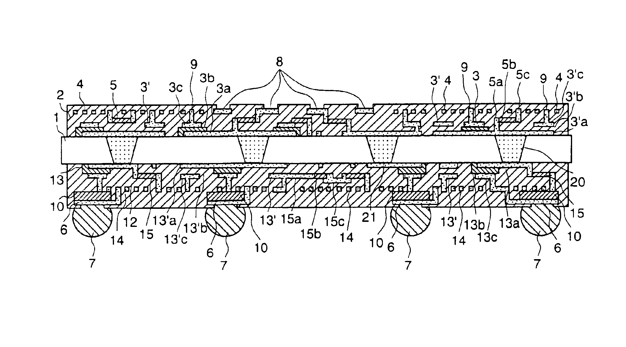
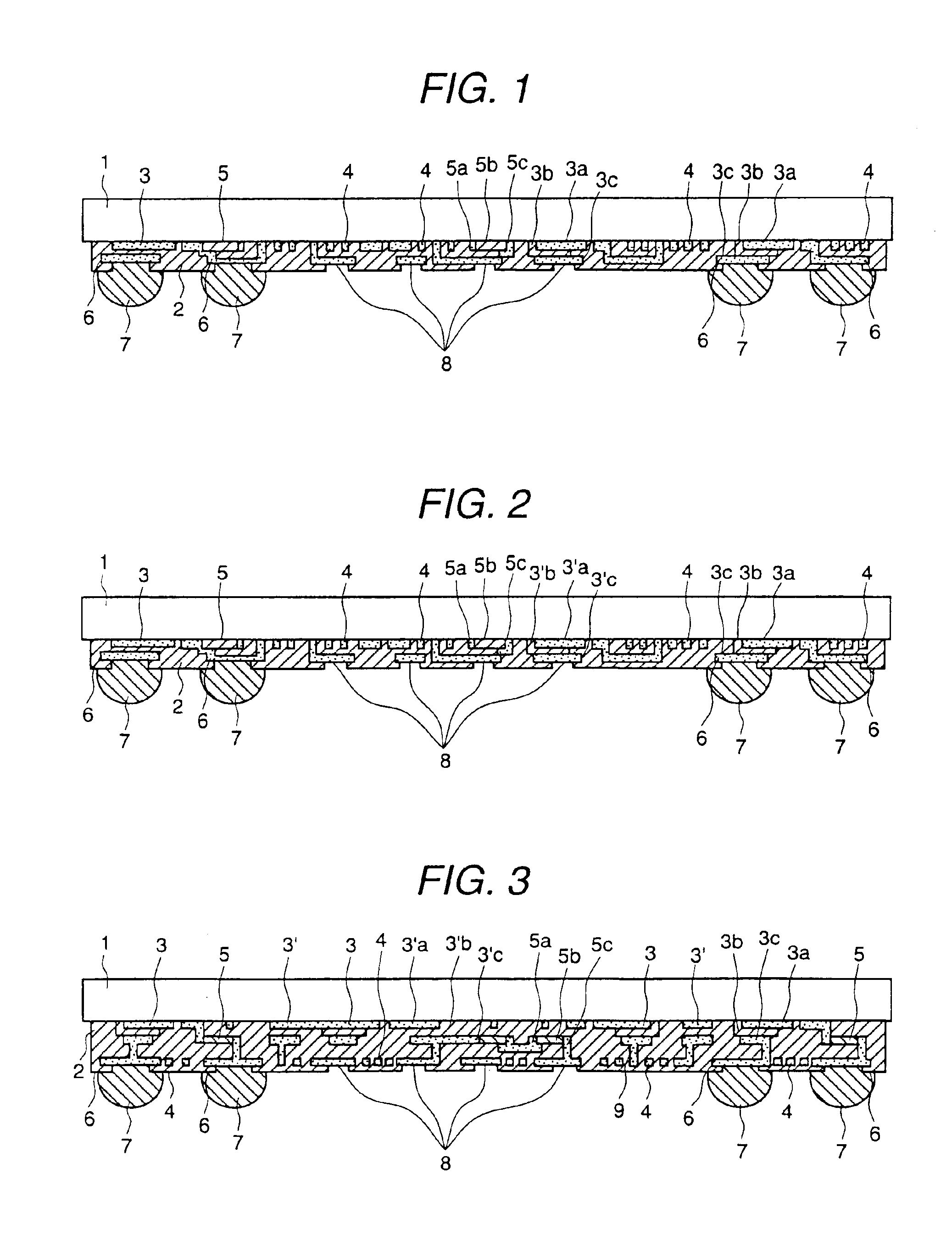
[0069]FIG. 1 is a cross sectional view of a semiconductor connection substrate representing one embodiment of the present invention. In FIG. 1, 1 is a glass substrate (product of Nippon Electric Glass Co., Ltd., BLC), and the thickness of which is 0.5 mm.

[0070]In FIG. 1, 2 is an organic insulator and photosensitive polyimide (product of Hitachi Chemical Co., Ltd., HD-6000) is used therefor.

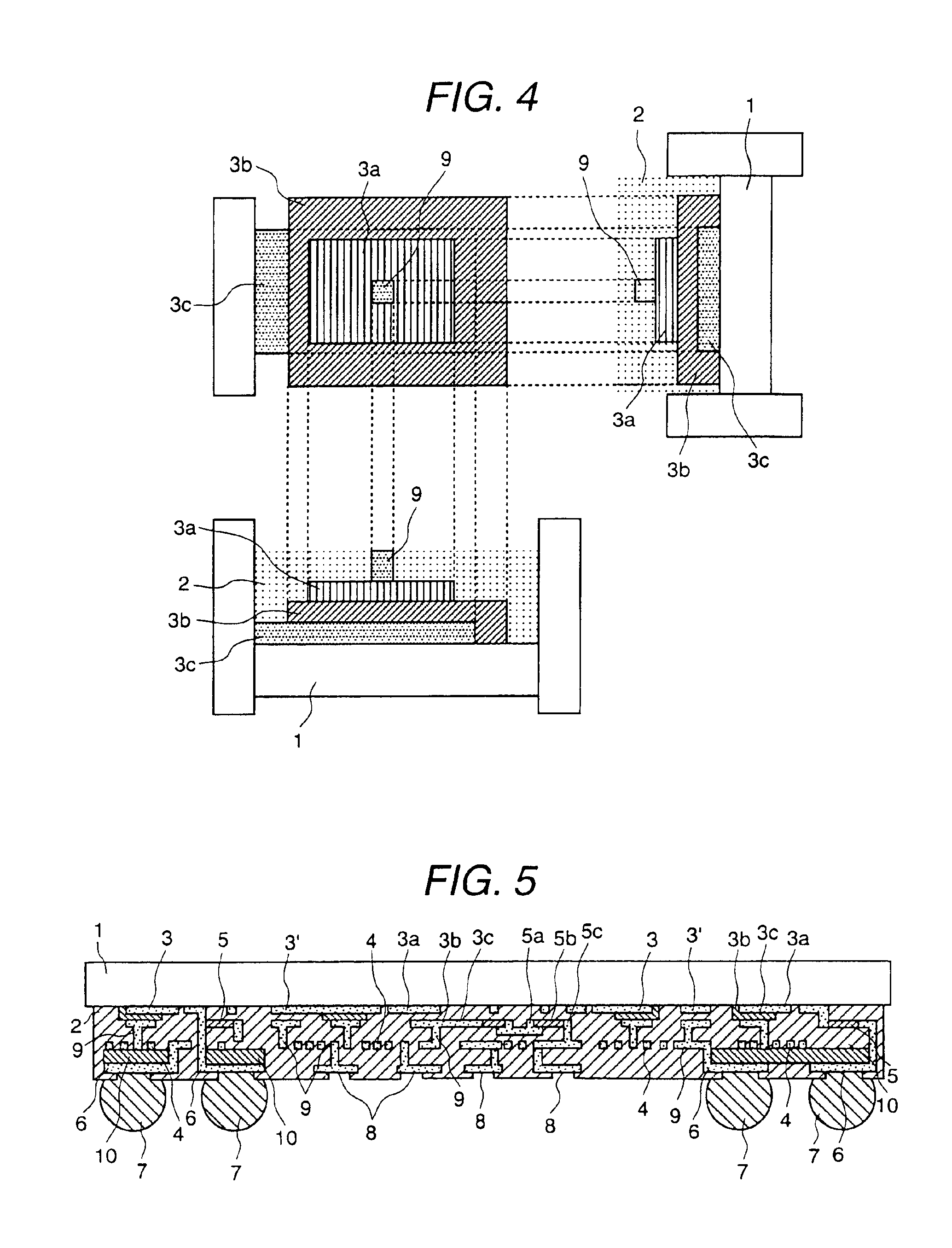
[0071]A capacitor element 3 formed inside the organic insulator 2 is in a three layer structure constituted by a lower electrode 3a, a dielectric body 3b and an upper electrode 3c. The lower electrode 3a is constituted by Cu, the dielectric body 3b by oxide of Ta and the upper electrode 3c by Cu.

[0072]An inductor element 4 is a spiral type inductor and is formed on the same plane as the upper electrode 3c of the capacitor element 3 and the material thereof is Cu.

[0073]A resistor 5 is constituted by a resistance body 5b and electrodes 5a and 5c. The resistance body 5b is a compound of...

embodiment 2

(Embodiment 2)

[0089]In embodiment 2, in place of the glass substrate 1 used in embodiment 1 in FIG. 1, the following glass substrate was used. The composition of the glass substrate of the present embodiment contains at least one rare earth element selected among the group including Sc, Y, La, Pr, Nd, Pm, Sm, Eu, Gd, Tb, Dy, Ho, Er, Tm, Yb and Lu in an amount of 0.5˜20 weight % with respect to the entire glass components when converted based on oxide of Ln2O3 (Ln is a rare earth element) and as the other components contains SiO2:40˜80 weight %, B2O3:0˜20 weight %, R2O (R2 is alkali metal):0˜20 weight %, RO (R is alkaline earth metal):0˜20 weight % and Al2O3:0˜17 weight %, and it is preferable that R2O+RO are contained in an amount of 10˜30 weight %. Further, the thickness thereof was 0.5 mm like embodiment 1.

[0090]Further, the portions other than the glass substrate 1 in the present embodiment are the same as those in embodiment 1.

[0091]Further, the manufacturing method of the semic...

embodiment 3

(Embodiment 3)

[0095]In embodiment 3, in place of the photosensitive polyimide used in embodiment 1, BCB (product of Dow Chemical, Cycloten 4026) was used as the organic insulator 2.

[0096]Further, the portions other than the organic insulator 2 in the present embodiment are the same as those in embodiment 1.

[0097]Further, the manufacturing method of the semiconductor connection substrate of the present embodiment is the same as that of embodiment 1.

[0098]The dielectric constant and dielectric loss tangent of BCB are respectively 2.65 and 0.003, which are respectively smaller than 3.5 and 0.01 of the photosensitive polyimide.

[0099]Accordingly, by using BCB as a insulator layer which covers the circumference of the electronic parts, the conductive loss and dielectric loss are reduced, thereby, loss of signals, passing through the electronic parts can be reduced.

[0100]Through the use of BCB for the organic insulator in the present embodiment, the conductive loss and dielectric loss are ...


PUM


Abstract

A semiconductor connection substrate which connects a semiconductor element to a mounting substrate such as a printed substrate comprises an insulator substrate, a plurality of electrodes having different areas provided on the insulator substrate, one or more elements selected from a capacitor element of dielectric material sandwiched between the electrodes, an inductor element and resistor element, a metal wiring connecting the elements, a metal terminal part of part of the metal wiring and an organic insulator material covering the elements and the circumference of the metal wiring portion excluding the metal terminal portion.

Description

FIELD OF THE INVENTION[0001]The present invention relates to an electronic part and a manufacturing method thereof. In particular, the present invention relates to a technology which is effective when applied to an electronic part having glass as the substrate and a corresponding manufacturing method.BACKGROUND ART[0002]JP-A-8-255981 discloses a technology in which an exposing process for a photo sensitive material with ultraviolet light is used to form microscopic via holes and wirings on a glass substrate. By forming a light shielding film of a metal such as Ti, Cr, Al, Ni, W, Mo, Ta and Cu on the glass substrate, multiple reflection of ultraviolet light between the upper and lower faces of the glass substrate is prevented at the time of the exposing process of the photo sensitive material. Further, by forming a light shielding film composed of one of the above metals having a thickness of more than 3 μm, the heat conductivity of the glass substrate is enhanced.[0003]JP-A-9-321184...

Claims


Application Information

Patent Timeline
Patent Type & Authority Patents(United States)
IPC IPC(8): H01L23/498H01L23/48H05K1/16H05K3/46
CPCH01L23/49816H01L23/49822H01L23/49827H01L23/49894H05K1/162H01L2924/12044H01L2924/19011H01L2924/3011H05K3/4602H05K2201/09509H05K2201/09763H01L2924/0002H01L2924/00
Inventor SATOH, TOSHIYAOGINO, MASAHIKOMIWA, TAKAONAITOU, TAKASHINAMEKAWA, TAKASHI
Owner RENESAS ELECTRONICS CORP
Why Eureka
Try Eureka