Optical connector and method of manufacturing the optical connector

a technology of optical connectors and manufacturing methods, applied in the field of optical connectors, can solve the problems of poor productivity, difficult insertion of optical fibers into optical fibers, and difficulty in achieving the dimensional accuracy of insertion holes, so as to prevent the occurrence of latent damage, enhance fabrication accuracy, and enhance productivity

Inactive Publication Date: 2005-11-17
KOHOKU KOGYO CO LTD
View PDF1 Cites 5 Cited by
  • Summary
  • Abstract
  • Description
  • Claims
  • Application Information

AI Technical Summary

Benefits of technology

[0014] Preferably, the method comprises the step of continuously conducting the formation of said insertion holes and the formation of said taper part of a predetermined angle by pulsed laser beam machining. More preferably, the pulsed laser beam is a femtosecond laser beam. The formation of the taper part continuous from the formation of the insertion holes can enhance the productivity.
[0015] More preferably, the method comprises the step of, in forming the insertion holes by pulsed laser beam machining, shaping the end of said insertion holes into a taper of a predetermined angle, more preferably by etching treatment with at least one inorganic acid selected from the group consisting of hydrofluoric acid, hydrochloric acid, nitric acid, and sulfuric acid. The etching treatment can enhance the fabrication accuracy and can realize smooth insertion of optical fibers to the insertion holes to prevent the occurrence of latent damage.

Problems solved by technology

In the case of conventional fiber arrays or ferrules manufactured by conducting injection molding or extrusion and then subjecting the molding to steps of baking and working, achieving the dimensional accuracy of insertion holes, into which optical fibers are to be inserted, within 1 μm is difficult due to the nature of the process.
This method, however, is disadvantageous in that the shape of the grind stone should always be corrected in order to keep the dimensional accuracy of V-shaped grooves or insertion holes on a constant level, resulting in poor productivity.
Further, ferrules using zirconia ceramic as the substrate suffer from a problem that working stress applied at the time of cutting causes transition of the crystal structure of the substrate and, consequently, the substrate is disadvantageously expanded, making it impossible to ensure the dimensional accuracy.

Method used


Image

  • Optical connector and method of manufacturing the optical connector
  • Optical connector and method of manufacturing the optical connector
  • Optical connector and method of manufacturing the optical connector

Examples


example 1

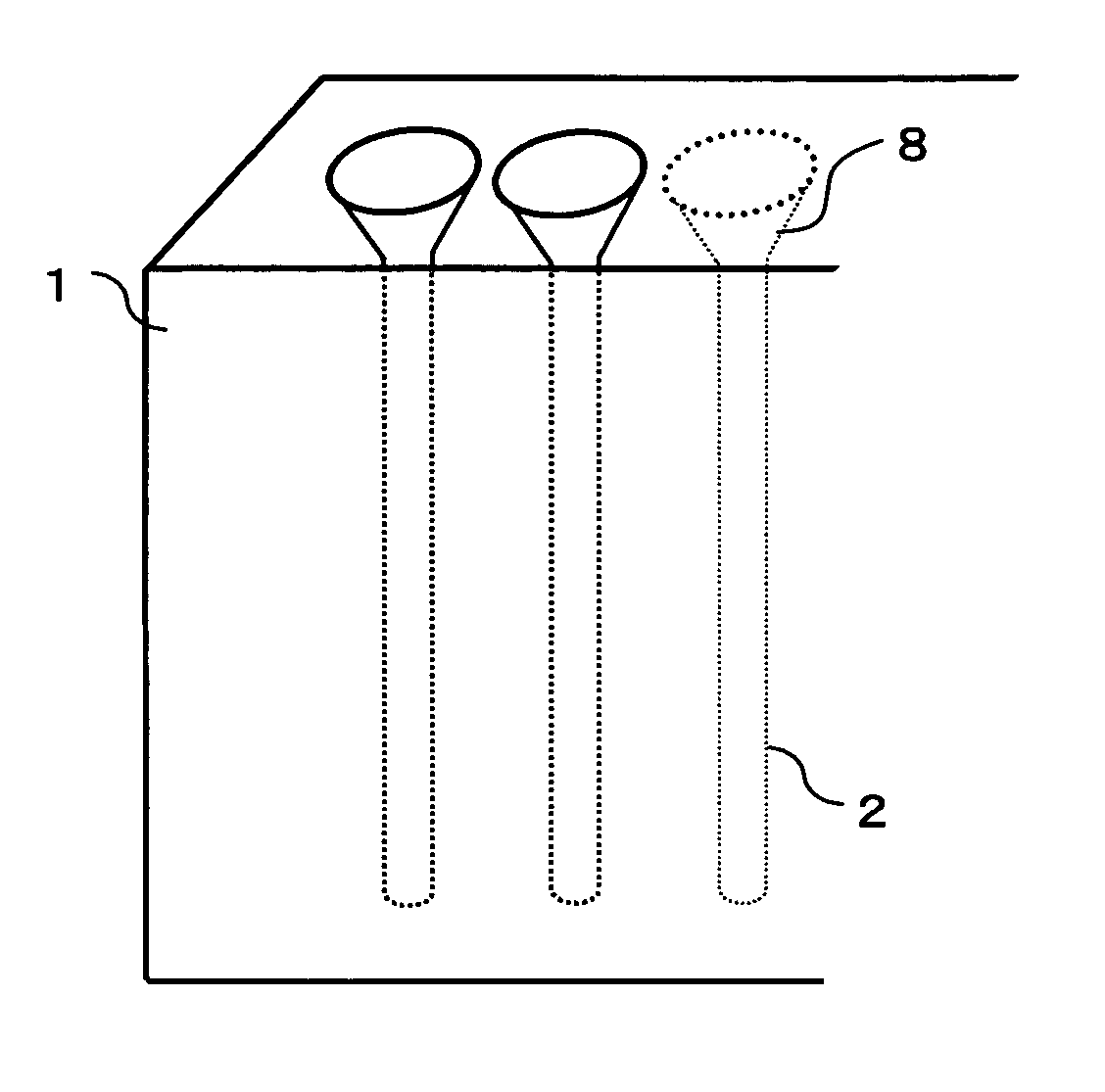
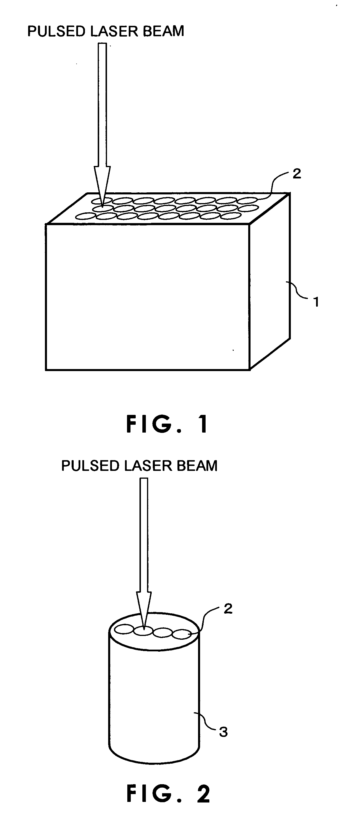
[0031] An LD excited Ti sapphire pulsed laser beam with a pulse repetition frequency of 1 kHz and a center wavelength of 800 nm was condensed with an objective lens (magnification: 5 times) to regulate the spot diameter to 125 μm. The laser beam was applied to a quartz glass cylindrical substrate (bandgap of the material: 7.9 eV), with a diameter of 3 mm and a height of 20 mm, having a laser irradiation face which had been subjected to optical polishing. Regarding irradiation conditions and machining speed, the pulse width was not more than 130 femtoseconds, the output was 200 mW, and the scanning speed was 100 μm. Four insertion holes were formed at intervals of 250 μm in the cylindrical substrate. Next, the cylindrical substrate with insertion holes formed therein was immersed in a 4 wt % aqueous hydrofluoric acid solution for one hr for etching with an ultrasonic cleaner. Thus, a four-core ferrule for optical communication was prepared.

[0032] The insertion holes of the ferrule f...

example 2

[0033] An LD excited Ti sapphire pulsed laser beam with a pulse repetition frequency of 1 kHz and a center wavelength of 800 nm was condensed with an objective lens (magnification: 5 times) to regulate the spot diameter to 125 μm. The laser beam was applied to a 5 mm-thick rectangular quartz glass substrate (bandgap of the material: 7.9 eV) having a laser irradiation face which had been subjected to optical polishing. Regarding irradiation conditions and machining speed, the pulse width was not more than 130 femtoseconds, the output was 200 mW, and the scanning speed was 100 μm. Ten insertion holes were formed at intervals of 250 μm in the substrate. Next, the cylindrical substrate with insertion holes formed therein was immersed in a 4 wt % aqueous hydrofluoric acid solution for one hr for etching with an ultrasonic cleaner. Thus, a ten-core fiber array for optical communication was prepared.

[0034] The insertion holes of the array for optical communication were cylindrical and had...

example 3

[0036] A ferrule for optical communication was prepared under the same machining conditions as in Example 2, except that, in the formation of the ten insertion holes, the interval of the insertion holes was changed to 125 μm.

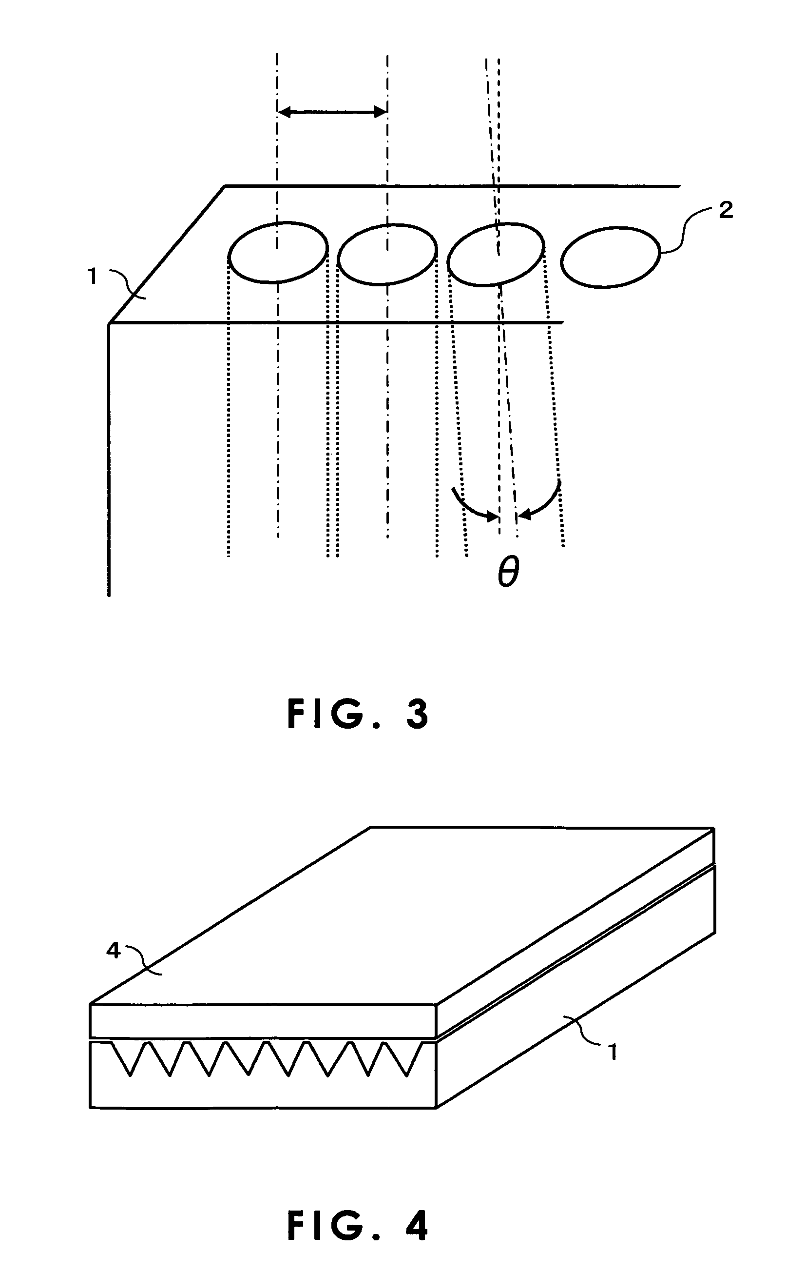
[0037] The insertion holes of the ferrule for optical communication were cylindrical and had an inner diameter of 125 μm. The distance between mutually adjacent insertion holes was 250 μm±0.4 μm, and the center-to-center dimension between both ends of the ten insertion holes was 1125 μm±0.4 μm. The degree of parallelization in the Z axis direction (direction perpendicular to laser beam irradiation face) of the insertion holes was ±0.07 degree. Further, it was confirmed that an about 60-degree taper part was formed in the insertion hole end on the laser irradiation side.

[0038] In the same manner as in Example 2, optical fibers were inserted and fixed through bonding to the fiber ferrule for optical communication, and the coupling loss was measured. As a result,...


PUM

PropertyMeasurementUnit
transparencyaaaaaaaaaa
diameteraaaaaaaaaa
diameteraaaaaaaaaa

Abstract

An optical connector capable of providing a multicore ferrule for optical communication or a fiber array for optical communication having a high dimensional accuracy and easily manufactured at a low cost, comprising a plurality of insert holes for inserting optical fibers therein arranged at specified intervals, characterized in that the accuracy of the center-to-center distances between the adjacent insert holes is within ±0.5 μm and a parallelism between the adjacent insert holes in hole axial direction is within ±0.1°.

Description

TECHNICAL FIELD [0001] The present invention relates to an optical connector for optical fiber connection, particularly a multi-core optical connector. BACKGROUND ART [0002] Increased speed and increased capacity of information transmission in recent years have led to widespread use of information communication using optical fibers. The information communication using optical fibers requires connection between optical fibers themselves or between an optical fiber and optical information equipment. Optical connectors such as ferrules for optical communication and fiber arrays for optical communication have been used for such connection. Demands for size reduction and high-density integration have led to a tendency toward the use of multi-core optical connectors. [0003] Due to the nature of the structure of the optical connector that optical fibers are fitted into and fixed to respective insertion holes formed in a substrate, in order to prevent connection loss of optical fibers, the ...

Claims


Application Information

Patent Timeline
Patent Type & Authority Applications(United States)
IPC IPC(8): G02B6/24B23K26/382G02B6/36G02B6/38
CPCG02B6/3644G02B6/3672G02B6/3834G02B6/3692G02B6/3688
Inventor QIU, JIANGRONHIRAO, KAZUYUKIYOSHIZAWA, SHUHEIYAJIMA, TAMOTSUISHII, FUTOSHI
Owner KOHOKU KOGYO CO LTD
Why Eureka
Try Eureka