Cooling fan with reinforced blade

a cooling fan and reinforced technology, applied in the field of circular devices, can solve the problems of affecting the efficiency of cooling fans, so as to improve the columnar properties of airflow and improve the design of airfoils

Inactive Publication Date: 2005-09-06
DELTA T
View PDF19 Cites 104 Cited by
  • Summary
  • Abstract
  • Description
  • Claims
  • Application Information

AI Technical Summary

Benefits of technology

[0013]In another embodiment, the aforementioned needs may also be satisfied by a metal fan blade for a fan assembly used in an industrial building. In this particular embodiment, the fan blade may comprise an extruded cross-sectional profile having a plurality of curved walls, wherein a first curved wall is joined to a second curved wall to form an airfoil shape having a trailing edge that includes a flange extending outward from the direction of the trailing edge, wherein the flanged portion of the trailing edge downwardly extends from the lower surface of the trailing edge such that the angular displacement of the flanged portion from the lower surface of the trailing edge forms a reinforced region that increases the structural rigidity of the trailing edge so that the flanged trailing edge resists damage, and wherein the flange increases the volume of airflow resulting from the operation of the fan assembly having the fan blade.
[0014]In still another embodiment, the aforementioned may also be satisfied by a fan assembly for cooling industrial buildings. In this particular embodiment, the fan assembly may comprise a mounting assembly having a rotatable hub that attaches the fan assembly to the ceiling of the industrial building. The fan assembly may further comprise a plurality of fan blades mounted to the rotatable hub, wherein each of the plurality of fan blades is at least 3 feet long and is formed of an extruded metal so as to have a first air foil section and a tapered trailing edge, wherein a flange is integrally formed at the end of the tapered trailing edge so as to reinforce the tapered trailing edge and so as to provide increased downward thrust during rotation of the fan blades. In one aspect, the fan blades are formed using an extrusion fabrication process, wherein the flange reinforces the tapered trailing edge during the extrusion fabrication process so that the tapered trailing edge resists tearing while being formed.
[0017]In another aspect, forcing the metal into the extrusion mold may produce at least one fan blade with a uniform cross-section. Moreover, forcing the metal into the extrusion mold may produce the at least one fan blade having a first surface and a second surface that combine to form the airfoil section, which enhances the columnar properties of the airflow produced by the at least one fan blade. Furthermore, forcing the metal into the extrusion mold may produce the at least one fan blade with an extended first surface that comprises at least one of the tapered trailing edge and the reinforcing flange, which results in an improved airfoil design. These and other objects and advantages of the present invention will become more apparent from the following description taken in conjunction with the accompanying drawings.

Problems solved by technology

People who work in large buildings, such as warehouses and airport hangers, are routinely exposed to working conditions that range from being uncomfortable to hazardous.
On a hot day, the inside air temperature may reach a point where a person is unable to maintain a healthy body temperature.
Moreover, many activities that occur in these environments, such as welding or operating internal combustion engines, create airborne contaminants that may be deleterious to those exposed.
The problem of cooling or circulating air in large buildings may not be solved by conventional air conditioning methods.
If such devices were used, the operating costs would be substantial.
Therefore, conventional air conditioning is not typically used in ventilation systems that serve to rapidly remove airborne contaminants, such as exhaust or smoke, and replace the contaminated air with fresh air from an outside source.
A drawback of using small diameter fans to circulate air is that the resulting airflow dramatically tapers-off at downstream locations.
Also, the large amount of electrical power required by the simultaneous use of these devices in great numbers negates their advantage as an inexpensive cooling system.
Moreover, a drawback to using large diameter fans is that they typically require specially constructed high-strength light-weight blades that may withstand large stresses caused by significant gravitational torques that increase with an increasing blade length to width aspect ratio.
Unfortunately, conventional drivetrain components may be susceptible to mechanical failure due to the substantially large torque produced by electric motors during their startup phase, which may decrease the reliability of large diameter fans.
Unfortunately, such extruded blades have unsupported trailing edges that may tear from deforming or warping during formation and cooling.
As a result, the aerodynamic features are shortened due to tearing created on longer unsupported trailing edges during fabrication, which reduces the overall performance of the large fan blades.
Therefore, the shortened trailing edges adversely impact the aerodynamic effectiveness of the large fan blades thereby potentially diminishing the efficiency of generated circulatory air flow within a structure.

Method used


Image

  • Cooling fan with reinforced blade
  • Cooling fan with reinforced blade
  • Cooling fan with reinforced blade

Examples


Embodiment Construction

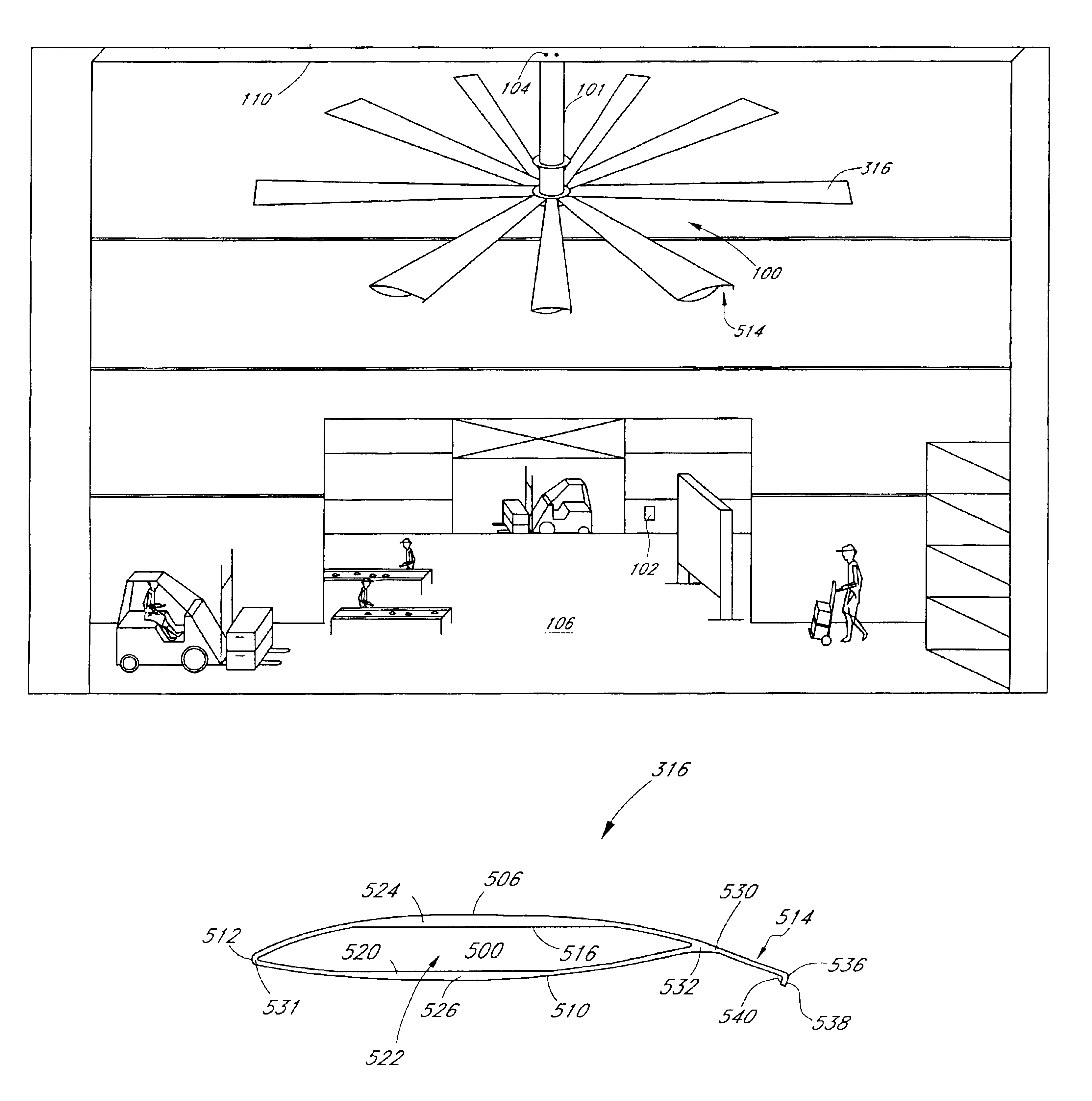
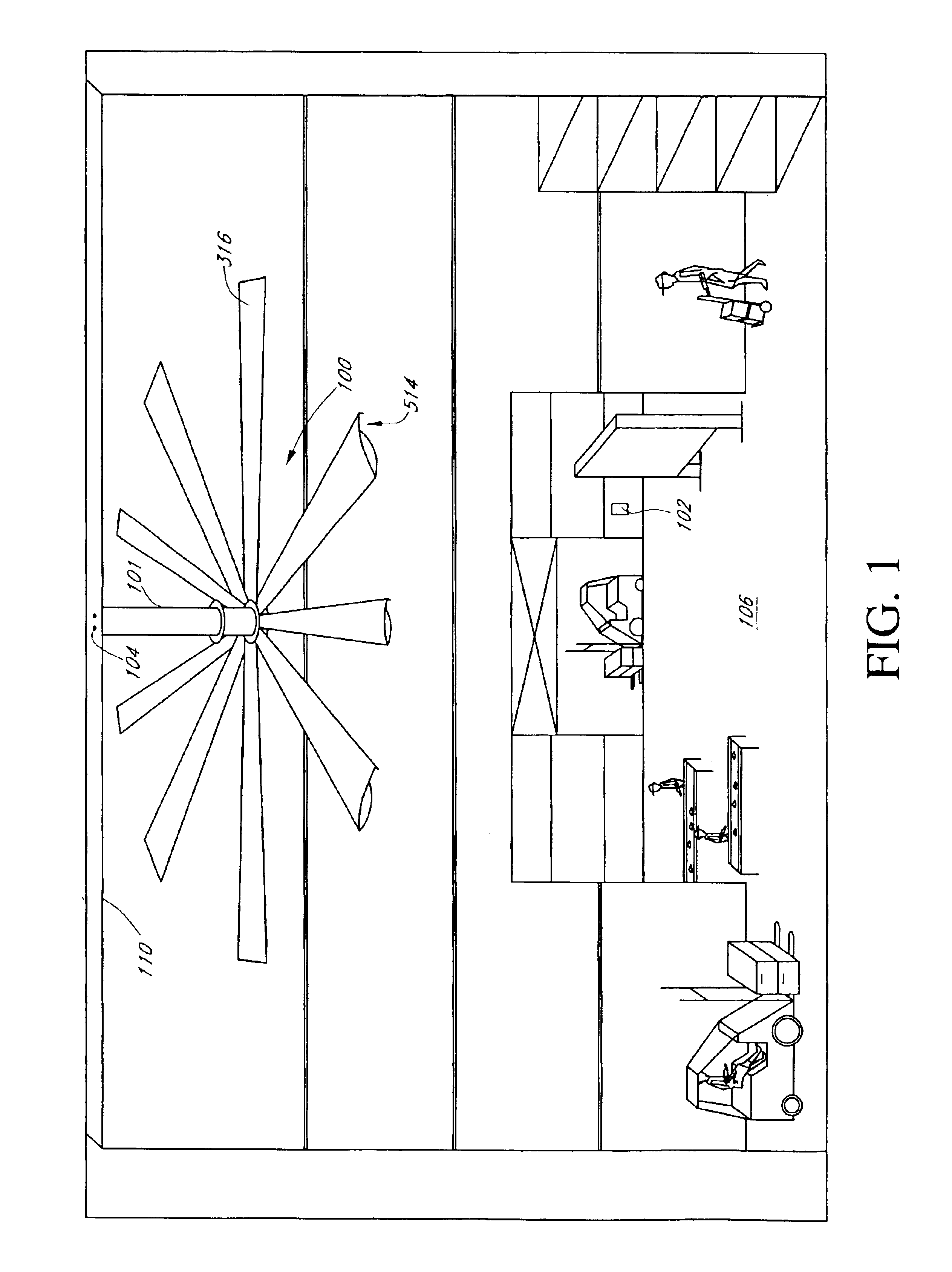
[0027]Reference will now be made to the drawings wherein like numerals refer to like parts throughout. FIG. 1 illustrates one embodiment of a fan assembly 100 having a plurality of fan blades 316 with each having a reinforced trailing edge 514 that may be positioned adjacent to the ceiling 110 of a large commercial and / or industrial building 106. In a manner as will be described in greater detail herein below, an extrusion process may be used to form each fan blade 316 with the reinforced trailing edge 514. In one aspect, the occurrence of trailing edge tearing to the fan blade 316 during extrusion may be reduced due to the supporting features of the reinforced trailing edge 514 in a manner that will be described in greater detail herein below.

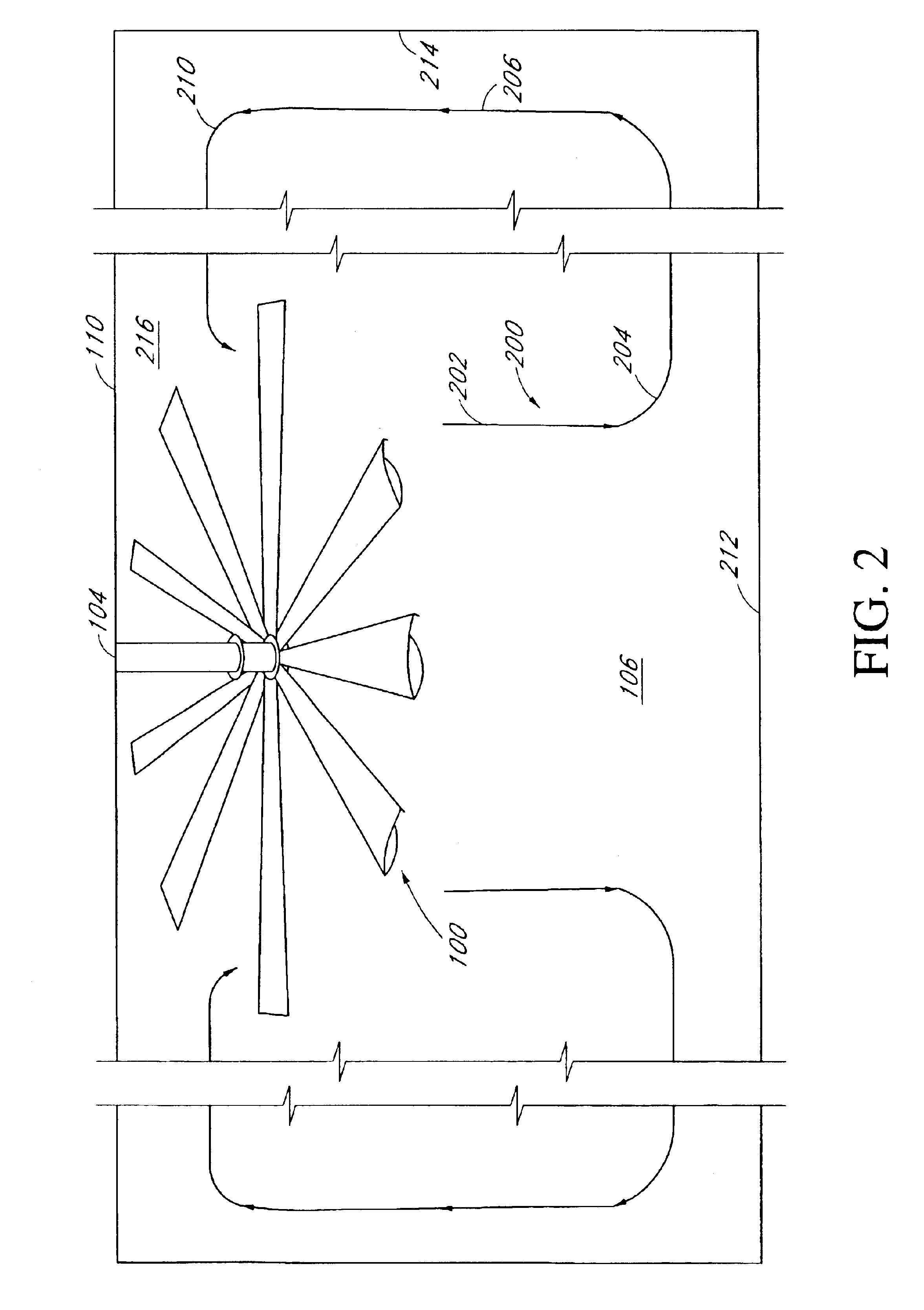
[0028]The fan assembly 100 may be attached to any suitable pre-existing supporting structure or to any suitable extension connected thereto in an overhead configuration such that the axis of rotation of the fan assembly 100 is along a substant...


PUM

PropertyMeasurementUnit
widthaaaaaaaaaa
widthaaaaaaaaaa
lengthaaaaaaaaaa

Abstract

A circulatory device comprising a large diameter fan having reinforced fan blades with a tapered airfoil shape is disclosed. The fan blades may be formed using an extrusion method of fabrication, wherein each fan blade may comprise a reinforced trailing edge with a downwardly extending flange. The benefit of forming each fan blade with a reinforced trailing edge of the present invention results in improved structural characteristics such that the trailing edge of each fan blade may be fabricated longer so as to improve aerodynamic performance. Also, the reinforced trailing edge resists tearing that may occur during extrusion by adding the bent flanged region to at least one distal end of the trailing edge. For example, the bent portion of the trailing edge tends to rigidly orient the extruded material in a stabilized position more readily during formation. Also, the bent portion provides added strength by providing supporting forces in two dimensions that relatively parallel and perpendicular to its length so as to neutralize the adverse effects of pressure forces acting on the trailing edge of the fan blade during extrusion.

Description

BACKGROUND OF THE INVENTION[0001]1. Field of the Invention[0002]The present invention relates to circulatory devices in large buildings and, in particular, concerns a cooling fan having reinforced blades that may be used to circulate a large volume of air.[0003]2. Description of the Related Art[0004]People who work in large buildings, such as warehouses and airport hangers, are routinely exposed to working conditions that range from being uncomfortable to hazardous. On a hot day, the inside air temperature may reach a point where a person is unable to maintain a healthy body temperature. Moreover, many activities that occur in these environments, such as welding or operating internal combustion engines, create airborne contaminants that may be deleterious to those exposed. The effects of airborne contaminants are magnified to an even greater extent if the area is not properly vented.[0005]The problem of cooling or circulating air in large buildings may not be solved by conventional ...

Claims


Application Information

Patent Timeline
Patent Type & Authority Patents(United States)
IPC IPC(8): F04D25/08B21C23/00B64C11/28B64C11/00B64C11/16B63H1/20B63H1/00F01D5/18F01D5/30F01D5/00F04D25/02F04D29/34F04D29/38F04D29/32F01D5/14F04D
CPCF01D5/147F04D25/088F04D29/388Y02T50/673Y02T50/671Y02T50/60F04D29/38F04D25/08
Inventor BOYD, WALTER
Owner DELTA T
Why Eureka
Try Eureka