
Porous material air bearing platen for chemical mechanical planarization

Inactive Publication Date: 2005-09-06
APPLIED MATERIALS INC
View PDF21 Cites 30 Cited by
  • Summary
  • Abstract
  • Description
  • Claims
  • Application Information

AI Technical Summary

Benefits of technology

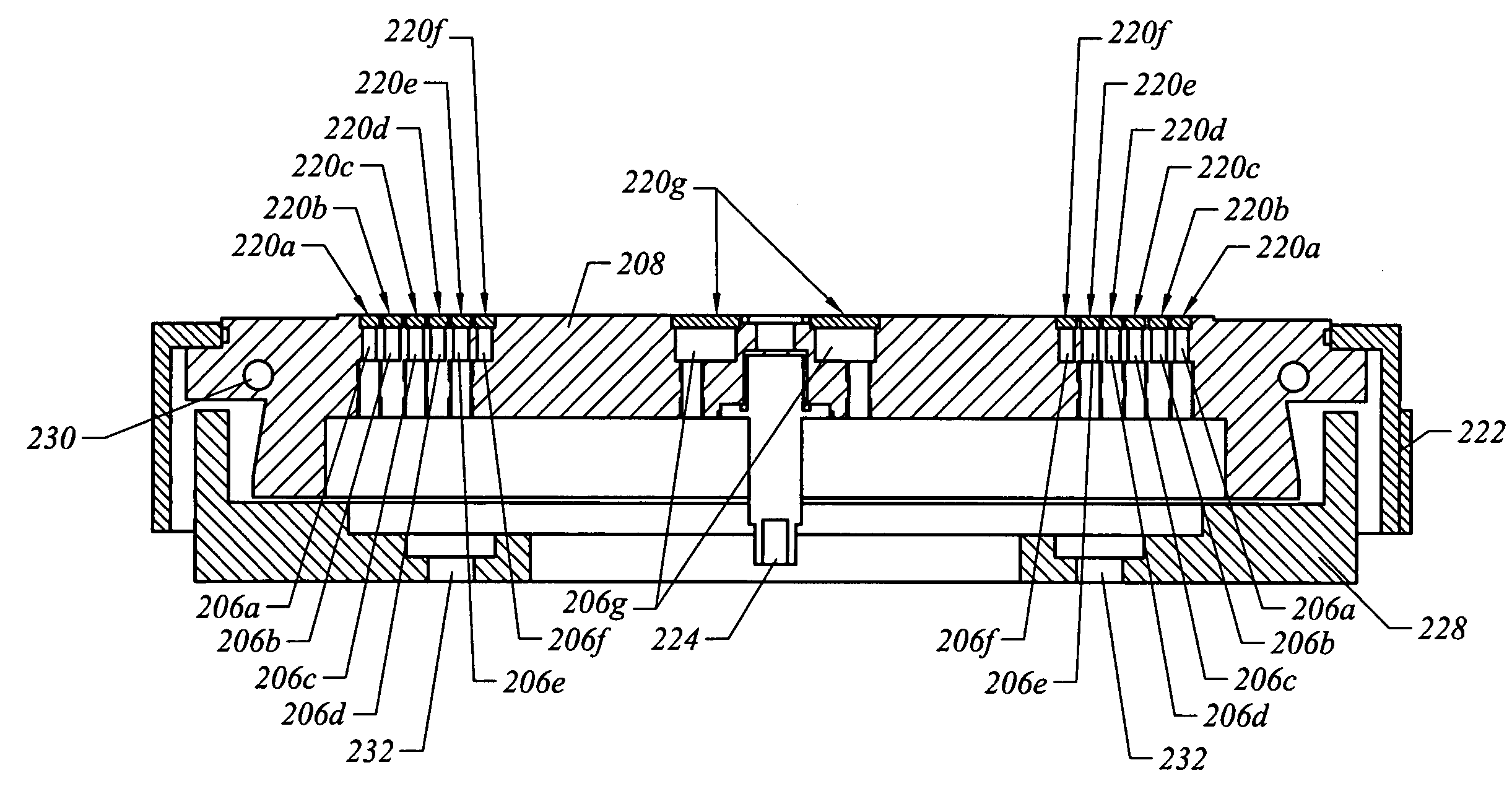
[0009]Broadly speaking, the platen described herein fills these needs by providing an apparatus for independently controlling air pressure above various portions of the air bearing platen during CMP and at the same time reducing air consumption by utilizing porous materials in the platen. The method involves using an improved air bearing platen with strategically utilized air ports underneath porous materials to powerfully control air pressure pushing on certain regions of the polishing pad with greatly reduced air consumption compared to prior art platens. In this way, polishing pressure in different sections of a wafer may be separately controlled which in turn enables precise control of polishing pad deformation during polishing. In addition, the platen reduces problems with large air consumption. It should be appreciated that the present invention can be implemented in numerous ways, including as a process, an apparatus, a system, a device or a method. Several inventive embodiments of the present invention are described below.
[0010]In a one embodiment, a platen for use in chemical mechanical planarization (CMP) systems includes a platen plate that has at least one recess defined therein. The at least one recess has an input port formed therein. A porous material is disposed in the at least one recess. The porous material has a porosity sufficient to restrict air flow therethrough so as to reduce an amount of air required for a CMP operation.
[0011]In another embodiment, a platen plate has a recess defined in a central region of the platen plate and a plurality of recesses defined in a peripheral region of the platen plate. The recess in the central region and each of the plurality of recesses defined in the peripheral region have an input port therein. The recess defined in the central region and each of the plurality of recesses defined in the peripheral region have an annular shape. The platen plate also includes a plurality of annular sections. One of the annular sections is disposed in the recess defined in the central region of the platen plate and the other of the annular sections are disposed in the plurality of recesses defined in the peripheral region of the platen plate. Each of the plurality of annular sections is comprised of porous material having a porosity sufficient to restrict air flow therethrough so as to reduce an amount of air required for a CMP operation.
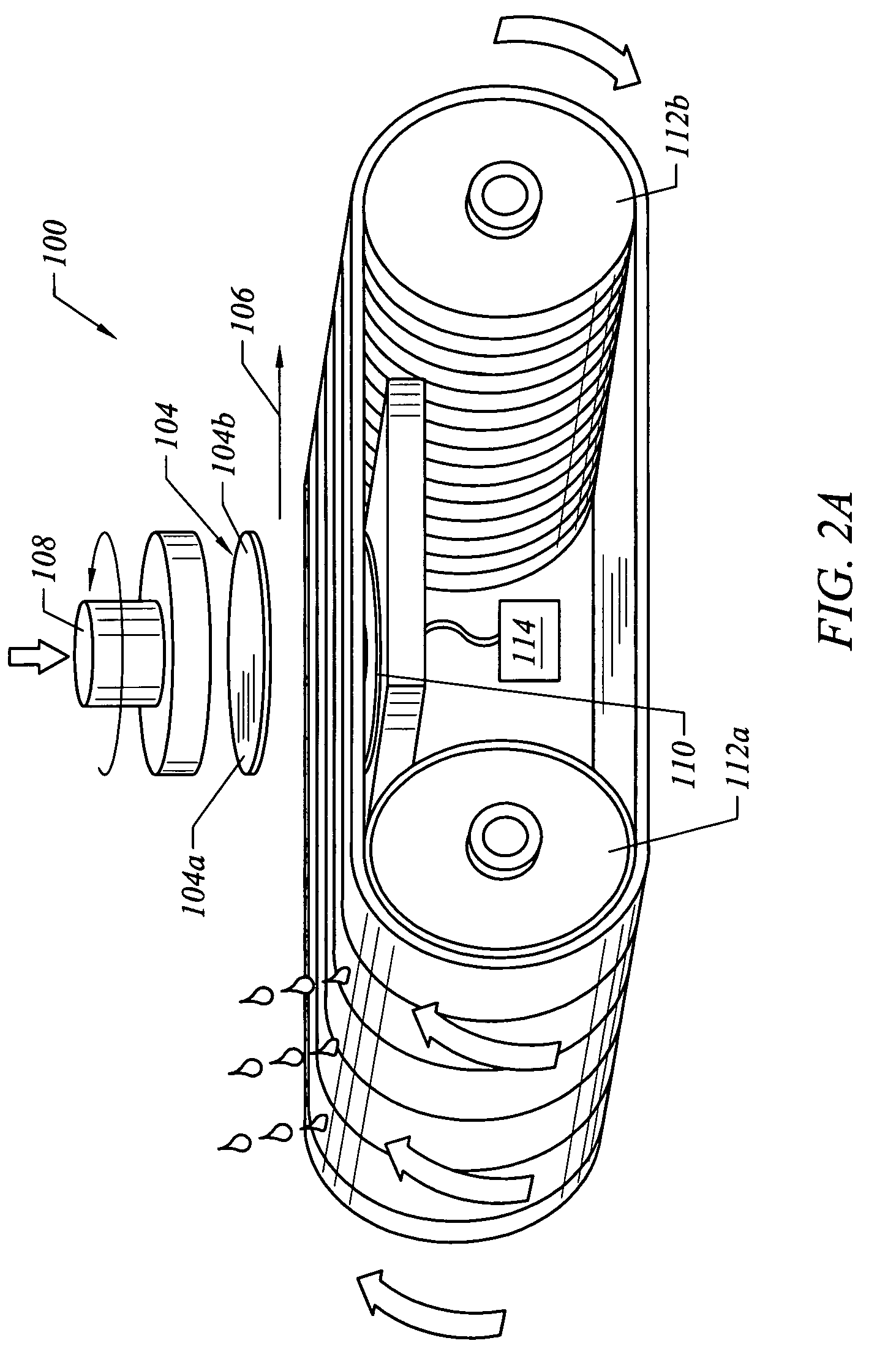
[0012]In yet another embodiment, a method for supplying air to an underside of a polishing belt in a chemical mechanical planarization (CMP) system includes providing a platen proximate to an underside of a polishing belt. At least a portion of the platen is formed of a porous material having a porosity sufficient to restrict air flow therethrough so as to reduce an amount of air required for a CMP operation. The method also includes flowing air through the porous material to the underside of the polishing belt.
[0013]The advantages of the present invention are numerous. Most notably, by creating an apparatus that is configured to control air pressure applied by a platen to a polishing belt while at the same time dramatically reducing air consumption by the platen, various air output regions in certain parts of the platen may be managed together or separately. In this way, the polishing pressure applied by the polishing belt to certain areas of a wafer may be effectively managed thereby optimizing polishing belt profile during CMP operations. Such intelligent management of polishing pressure enables attainment of an optimal wafer polishing profile. In addition, the platen described herein includes a porous material configured to cover the various air output ports within the platen. By placing the porous material over the output regions, air does not flow freely through the porous material thereby decreasing air usage by the platen during the generation of an air bearing in a CMP process. But through consistent application of air pressure applied to the porous material, air pressure desired to create the air bearing for wafer polishing may be attaned. Consequently, the present inventions enable optimal air bearing generation but also consumes much less air than conventional platens.

Problems solved by technology

Without planarization, fabrication of further metallization layers becomes substantially more difficult due to the variations in the surface topography.
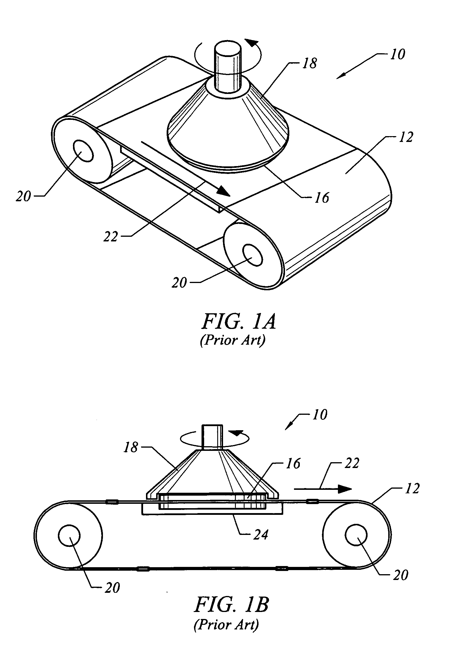
Unfortunately, because the polishing pressure produced by a typical air bearing with air holes interspersed uniformly throughout the platen typically cannot be controlled very well, the polishing pressure applied by the air bearing to different parts of the wafer 16 generally cannot be separately managed.
Hence, conventional air bearings generally do not accurately control wafer polishing on the leading and trailing edges of the wafer 16.
In addition, typical air bearing platens utilize a very large amount of air.
Consequently, prior art air bearing platens have a problem of large air consumption.

Method used


Image

  • Porous material air bearing platen for chemical mechanical planarization
  • Porous material air bearing platen for chemical mechanical planarization
  • Porous material air bearing platen for chemical mechanical planarization

Examples


Embodiment Construction

[0023]Several exemplary embodiments of the invention will now be described in detail with reference to the accompanying drawings. FIGS. 1A and 1B are discussed above in the “Background of the Invention” section.

[0024]In summary, a platen for use in chemical mechanical planarization includes a platen plate with a plurality of recesses. A porous material is disposed over the recesses so optimal air pressure may be maintained on an underside of a polishing belt during CMP operations without consumption of large amounts of air. The porous material has a porosity sufficient to restrict air flow through it so as to reduce air usage for CMP operations. Therefore, the polishing pressure on wafers may be optimized and air consumption is dramatically reduced.

[0025]It should be understood that the platen described herein may be utilized to optimize air usage and to generate optimal air pressure on any suitable polishing pad structure such as, for example, a linear polishing belt. The platen ma...


PUM


Abstract

A platen for use in chemical mechanical planarization (CMP) systems includes a platen plate that has at least one recess defined therein. The at least one recess has an input port formed therein. A porous material is disposed in the at least one recess. The porous material has a porosity sufficient to restrict air flow therethrough so as to reduce an amount of air required for a CMP operation.

Description

BACKGROUND OF THE INVENTION[0001]The present invention relates to chemical mechanical planarization (CMP) techniques and, more particularly, to the efficient, cost effective, and improved CMP operations.[0002]In the fabrication of semiconductor devices, there is a need to perform chemical mechanical planarization (CMP) operations. Typically, integrated circuit devices are in the form of multi-level structures. At the substrate level, transistor devices having diffusion regions are formed. In subsequent levels, interconnect metallization lines are patterned and electrically connected to the transistor devices to define the desired functional device. As is well known, patterned conductive layers are insulated from other conductive layers by dielectric materials, such as silicon dioxide. As more metallization levels and associated dielectric layers are formed, the need to planarize the dielectric material grows. Without planarization, fabrication of further metallization layers becomes...

Claims


Application Information

Patent Timeline
IPC IPC(8): B24B21/04B24B37/04
CPCB24B21/04B24B37/14
Inventor PHAM, XUYEN
Owner APPLIED MATERIALS INC
Learn More