Optical fiber for transmitting ultraviolet ray, optical fiber probe, and method of manufacturing the optical fiber probe

a technology of optical fiber and ultraviolet ray, which is applied in the direction of manufacturing tools, glass optical fibre, instruments, etc., can solve the problems of unavoidable deterioration of conventional optical fiber, large size of the excimer laser, and large size of the exposure device equipped with the excimer laser, etc., and achieve the effect of etching more efficiently

Inactive Publication Date: 2005-09-13
JAPAN SCI & TECH CORP
View PDF11 Cites 86 Cited by
  • Summary
  • Abstract
  • Description
  • Claims
  • Application Information

AI Technical Summary

Benefits of technology

[0020]The optical fiber of the present invention for transmitting ultraviolet ray has a high transmittance for ultraviolet ray and is resistant to deterioration by ultraviolet ray when irradiated therewith, because it has the core of silica glass containing a given content of fluorine, and clad of silica glass containing a given content of fluorine or boron, of resin which transmits ultraviolet ray, or with two or more air holes arranged in parallel to the optical axis. Therefore, it can be suitably used for, e.g., an excimer laser and excimer lamp which use ultraviolet ray, and can reduce size of the exposure device which uses the excimer laser, and surface cleaning device which uses the excimer lamp.
[0025]The method of the present invention for producing the optical fiber for transmitting ultraviolet ray impregnates the fiber with hydrogen after the drawing step to enhance the effect of preventing its deterioration in particular when it is irradiated with ultraviolet ray, giving the optical fiber applicable to transmission of deep and vacuum ultraviolet ray.
[0032]The optical fiber probe of the present invention can transmit deep ultraviolet and vacuum ultraviolet ray at a high transmittance, is resistant to deterioration by deep ultraviolet and vacuum ultraviolet ray when irradiated therewith, and stably serviceable for extended periods, because its optical fiber has, e.g., the core of silica glass containing a given content of fluorine and clad of silica glass containing a given content of fluorine over the core.
[0035]The optical fiber can be etched more efficiently by the method of the present invention for producing the optical fiber probe than the conventional one provided with the core of germanium-containing silica glass, because it has the fluorine-containing core and clad, and etched with an aqueous solution of hydrofluoric acid as the etchant solution. Therefore, the method of the present invention for producing the optical fiber probe can sharpen the optical fiber end to a desired shape.

Problems solved by technology

Therefore, the exposure device equipped with an excimer laser tends to be large-sized due to necessity for providing the light path kept vacuum or filled with an inert gas.
However, the conventional optical fiber is deteriorated when irradiated with ultraviolet ray.
Nevertheless, deterioration represented by that of transmittance T5 is unavoidable.
Therefore, the conventional optical fiber is inapplicable to transmission of ultraviolet ray, because of its rapid deterioration by the transmission of ultraviolet ray.
However, the optical fiber probe of the above structure is difficult to propagate the so-called vacuum ultraviolet ray having a wavelength of 200 nm or less and so-called deep ultraviolet ray having a wavelength of 200 to 300 nm, which is one of its major disadvantages, because it is greatly deteriorated by the transmission of the vacuum or deep ultraviolet ray and is not fit for such ray.
However, the conventional etching method has a disadvantage that it cannot efficiently etch the optical fiber, because it is composed of the core of silica glass covered with clad, and is difficult to have a desired shape of the sharpened section at the fiber end.

Method used


Image

  • Optical fiber for transmitting ultraviolet ray, optical fiber probe, and method of manufacturing the optical fiber probe
  • Optical fiber for transmitting ultraviolet ray, optical fiber probe, and method of manufacturing the optical fiber probe
  • Optical fiber for transmitting ultraviolet ray, optical fiber probe, and method of manufacturing the optical fiber probe

Examples


example 1

[0071]A fluorine-doped silica glass (a trade name: AOX made by Asahi Glass Company) containing fluorine at 100 to 200 ppm and OH group at 4 to 7 ppm was used for the core, and silica glass containing fluorine at 2,000 ppm was used for the clad. The core and clad were produced to have a diameter of 600 and 750 μm, respectively. The optical fiber was treated with hydrogen, and irradiated with ultraviolet ray of varying wavelength emitted from an ArF excimer, to measure its transmittance at each wavelength before and after it was irradiated with ultraviolet ray running the unit length (1 m) of the fiber.

[0072]FIG. 7 shows the measurement results. As shown, the transmittance of the optical fiber remained essentially the same before and after it was irradiated with ultraviolet ray, T1 versus T2, indicating that the optical fiber for transmitting ultraviolet ray showed little deterioration even when it was irradiated with ultraviolet ray.

[0073]The optical fiber not treated with hydrogen w...

example 2

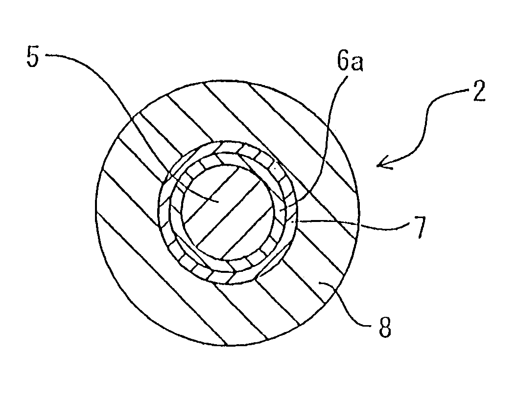
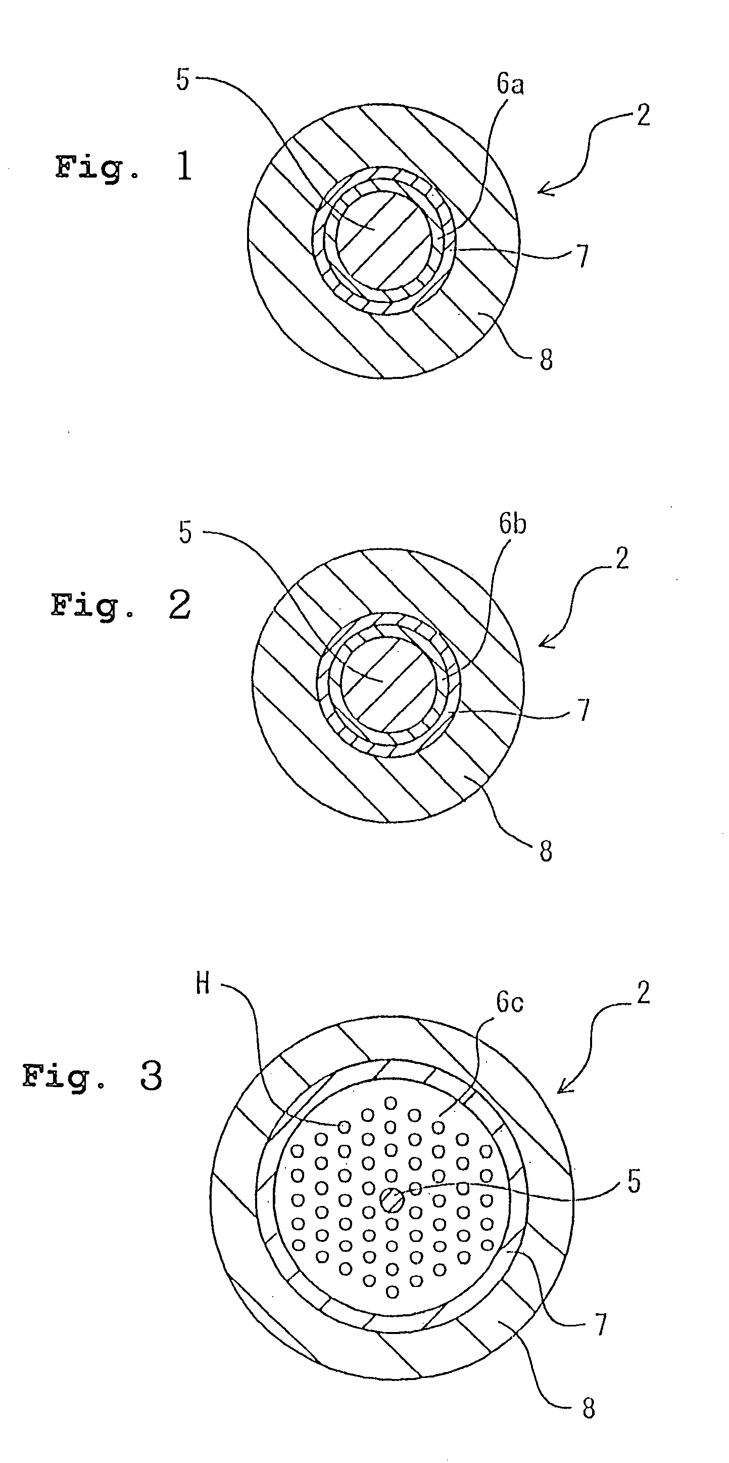
[0084]In the Example, a fluorine-doped silica glass (a trade name: AOX made by Asahi Glass Company) containing fluorine at 100 to 200 ppm and OH group at 4 to 7 ppm was used for the core 5, and silica glass containing fluorine at 2,000 ppm was used for the clad 6a formed over the core 5. The core and clad were produced to have a diameter of 10 and 125 μm, respectively. In COMPARATIVE EXAMPLE, the optical fiber composed of the 10 μm-diameter core of silica glass and 125 μm-diameter clad of silica glass was prepared. The end of each of these optical fibers was cut in the direction perpendicular to the optical axis, and the covered layer for protection 8 and protective layer 7 of given length (around 1 cm) from the cut section end were separated, to clean the external surfaces of the clad 6a. Next, the end section of each of these fibers of the EXAMPLE and COMPARATIVE EXAMPLE was immersed in a 30% aqueous solution of hydrofluoric acid 10, held in the container 9, to etch the section. T...


PUM

PropertyMeasurementUnit
wavelengthaaaaaaaaaa
diameteraaaaaaaaaa
diameteraaaaaaaaaa

Abstract

It is an object of the present invention to provide an optical fiber for transmitting ultraviolet ray which has an improve transmittance and is prevented from deterioration by ultraviolet ray with which it is irradiated. It is another object of the present invention to provide an optical fiber probe which can propagate vacuum ultraviolet ray and deep ultraviolet ray at a high transmittance, is deteriorated only to a limited extent when irradiated with ultraviolet ray and can be etched to have a desired shape of the sharpened section at the fiber end.The present invention provides the optical fiber for transmitting ultraviolet ray which has a core 5 of silica glass containing a given content of fluorine and a clad 6a of silica glass containing a given content of fluorine or boron, a clad 6b of a resin which transmits ultraviolet ray or a clad 6c having air holes H. The clad may be coated with a protective layer and further with a covered layer for protection. In particular, the core, clad and protective layer have a high transmittance for ultraviolet ray and resistance to ultraviolet ray with which they are irradiated, when treated with hydrogen.An optical fiber probe 1 has an optical fiber 2 provided with a sharpened section 3 at the end, which is sharpened with an etchant solution, the sharpened section 3 being coated with a light-shielding metallic film 4.

Description

CROSS-REFERENCE TO RELATED APPLICATION[0001]This application is a National Phase Application (35 USC 371) of PCT / JP02 / 00123 and claims priority of Japanese Application No. 2001-7111 filed Jan. 16, 2001 and Japanese Application No. 2001-248684 filed Aug., 2001.TECHNICAL FIELD[0002]This invention relates to optical fiber for transmitting ultraviolet ray, optical fiber probe, and methods of producing the same, more particularly the optical fiber for transmitting ultraviolet ray capable of transmitting the ray having a wavelength of 300 nm or less, optical fiber probe suitable as the one for scanning near field optical microscopes (SNOMs), and methods of producing the optical fiber for transmitting ultraviolet ray and optical fiber probe.BACKGROUND OF THE INVENTION[0003]Optical fibers have been used for information transmission or the like, and medical equipment and semiconductor production lines, e.g., for excimer laser used for lithography for semiconductor production lines.[0004]An o...

Claims


Application Information

Patent Timeline
Patent Type & Authority Patents(United States)
IPC IPC(8): C03B37/012C03B37/02C03C13/04C03C23/00C03C25/60C03C13/00C03B37/027C03C4/00C03C25/10G02B6/24G02B6/10G02B6/02C03C25/105C03C25/1065C03C25/607G02B6/26
CPCC03B37/01205C03B37/027C03B37/02781C03C4/0085C03C13/045C03C13/046C03C23/0095C03C25/1045C03C25/607G02B6/02333G02B6/02347G02B6/102G02B6/241G02B6/262C03B2201/10C03B2201/12C03B2201/21C03B2203/14C03B2203/42C03C2201/10C03C2201/12C03C2201/14C03C2201/21G02B6/02033G02B6/03694G02B6/02395C03C25/105C03C25/1065
Inventor HIDEO, HOSONOMASAHIRO, HIRANOMASANORI, OTOGEN, TOCHITANISUSUMU, OHNEDASHINNYA, KIKUGAWA
Owner JAPAN SCI & TECH CORP
Why Eureka
Try Eureka