Method for compensating injection quality in each individual cylinder in internal combustion engines

a technology of injection quality and internal combustion engine, which is applied in the direction of electrical control, process and machine control, instruments, etc., can solve the problems of high rejection quantity during manufacturing, and impaired measurement accuracy. , to achieve the effect of large tolerances, high rejection quantity, and high requirements on the flow tolerance of injectors

Inactive Publication Date: 2005-09-20
ROBERT BOSCH GMBH
View PDF11 Cites 7 Cited by
  • Summary
  • Abstract
  • Description
  • Claims
  • Application Information

AI Technical Summary

Benefits of technology

[0019]One advantage of the present invention is the possibility of using injectors with far larger tolerances.
[0020]In conventional injection systems, the requirements on the flow tolerance of injectors are very high, resulting in correspondingly high reject quantities during manufacturing.
[0021]The adjustment method according to the present invention allows proper adjustment of the injection quantities of the individual cylinders even in the case of markedly different flow characteristics of different injectors, making it possible to set lambda to the optimum value for exhaust-gas aftertreatment.
[0022]Thus, the method according to the present invention also reduces the manufacturing costs of injection systems and, at the same time, improves the emission performance by using more cost-effective injectors with larger tolerances, and eliminates the influences of these

Problems solved by technology

In this manner, the injection quantity can, in principle, be controlled individually for each cylinder by a single lambda sensor, but the measuring accuracy is impaired by mixing effects and turbulences of immediately successive exhaust quantities of different cylinders in the exhaust pipe.
Design approaches in which each cylinder is assigned a lambda sensor are technically very complex.
In conventional injection systems, the requirements on the flow tolerance of injectors are ver

Method used


Image

  • Method for compensating injection quality in each individual cylinder in internal combustion engines
  • Method for compensating injection quality in each individual cylinder in internal combustion engines
  • Method for compensating injection quality in each individual cylinder in internal combustion engines

Examples


Embodiment Construction

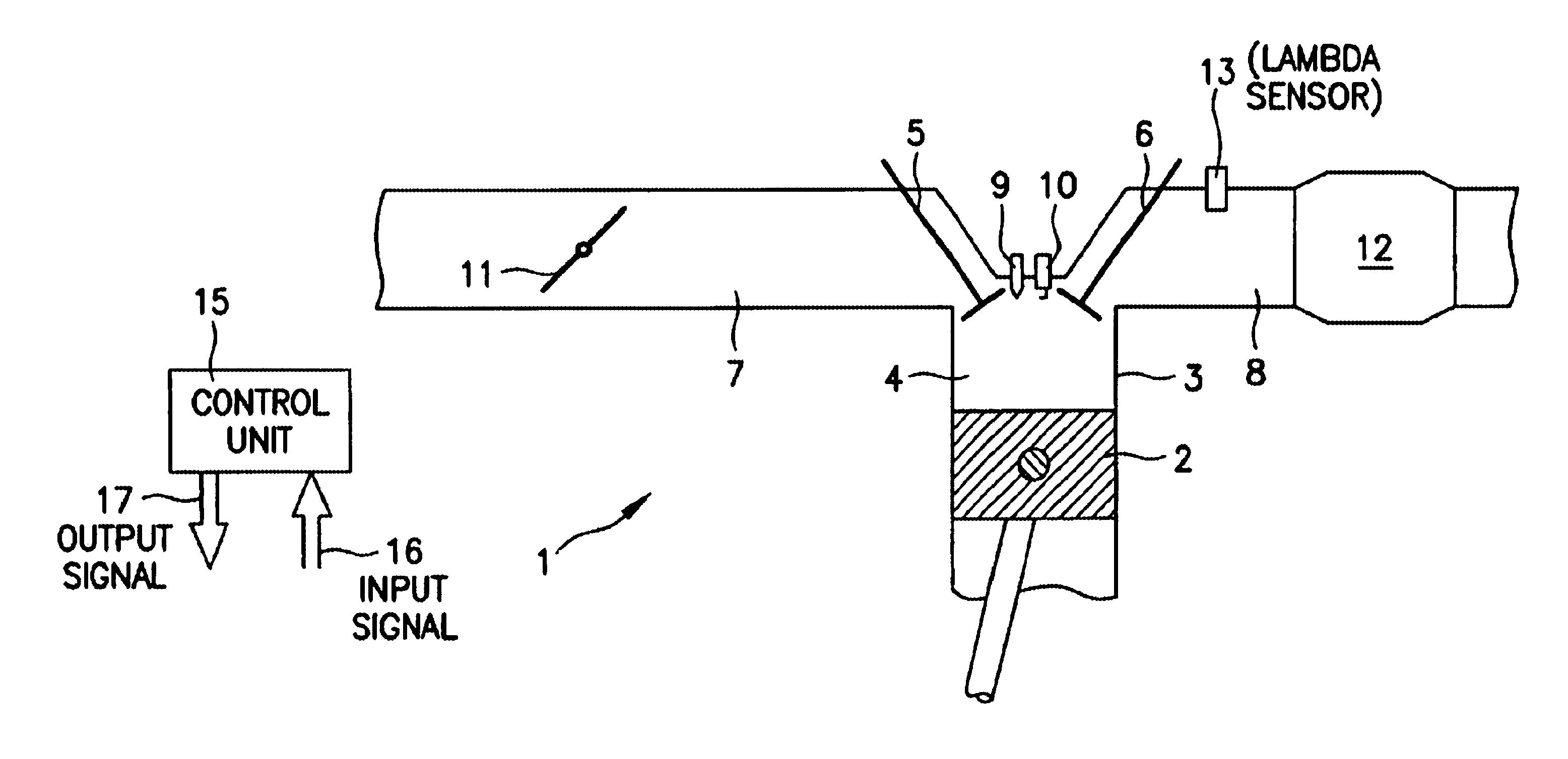
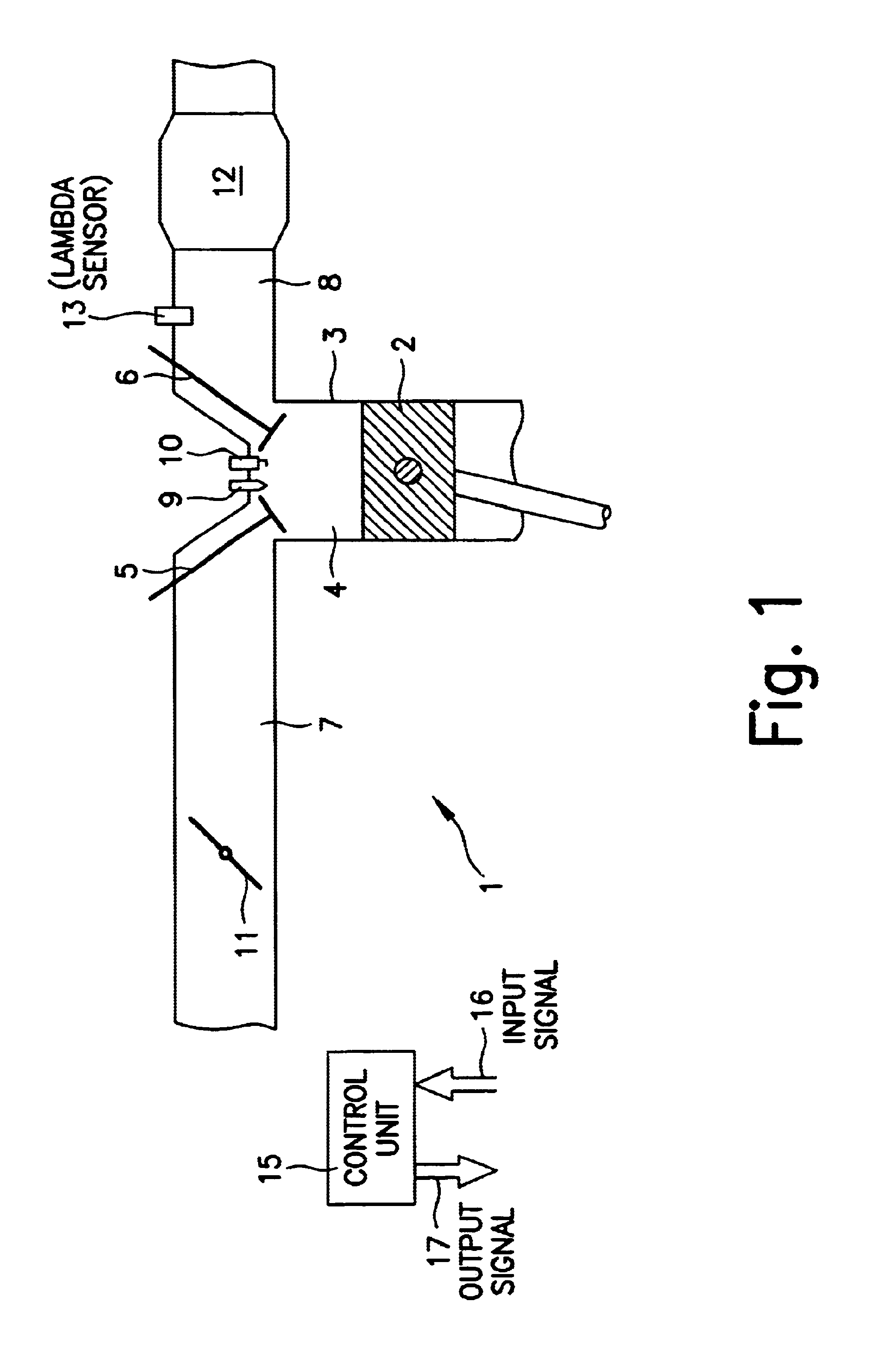
[0034]FIG. 1 shows an internal combustion engine 1 of a motor vehicle, in which a piston 2 is able to move back and forth in a cylinder 3. Cylinder 3 is provided with a combustion chamber 4, which is bounded, inter alia, by piston 2, an intake valve 5, and an exhaust valve 6. An intake pipe 7 is coupled to intake valve 5, and an exhaust pipe 8 is coupled to exhaust valve 6.

[0035]In the region near intake valve 5 and exhaust valve 6, an injector 9 and a spark plug 10 extend into combustion chamber 4. Injector 9 can also be located in intake pipe 7.

[0036]Fuel can be injected into the combustion chamber 4 through injector 9. The fuel in combustion chamber 4 can be ignited by spark plug 10.

[0037]Accommodated in intake pipe 7 is a rotatable throttle blade 11, by means of which air can be supplied to intake pipe 7. The quantity of supplied air depends on the angular position of throttle blade 11. The exhaust connectors of the individual cylinders 3 merge upstream of catalytic converter 12...


PUM


Abstract

A method for cylinder-specific adjustment of the injection quantity in internal combustion engines is provided, as well as an internal combustion engine with which the method may be implemented. The injection quantity per cylinder selected by the engine management is changed in a controlled manner following an orthogonal experimental plan. The effect of this change on the excess-air factor “lambda” is analyzed, allowing the formulation of a regression polynomial to determine necessary corrections of the injection quantity, which injection quantity is adjustable individually for each cylinder with a view to optimum combustion.

Description

FIELD OF THE INVENTION[0001]The present invention relates to a method for operating an internal combustion engine, in particular of a motor vehicle, in which method fuel is injected into the cylinders of the internal combustion engine, the fuel quantity injected into the individual cylinders being adjusted and in which method a lambda value is detected in the exhaust pipe of the internal combustion engine. Moreover, the present invention relates to an internal combustion engine that is suitable for carrying out this method.BACKGROUND INFORMATION[0002]For pollutant minimization in catalytic aftertreatment of exhaust gases with the aid of a closed-loop, three-way catalytic converter, it is known in the art that the air-fuel mixture should have a specific mass ratio. This ratio is indicated by the so-called excess-air factor “lambda”, and can be detected by a lambda sensor located in the exhaust pipe.[0003]In known methods, the values measured by the lambda sensor are fed to a control ...

Claims


Application Information

Patent Timeline
IPC IPC(8): F02D41/14F02D41/00F02D41/24F02D41/34F02D41/02F02D45/00F02D41/36
CPCF02D41/008F02D41/1456F02D41/2438F02D41/2467F02D41/2477F02D41/34
Inventor DEIBERT, RUEDIGERPREUSSNER, CHRISTIAN
Owner ROBERT BOSCH GMBH
Why Eureka
Try Eureka