Electrostatic chuck and manufacturing method therefor
a technology of electrostatic chuck and manufacturing method, which is applied in the direction of electrostatic holding device, basic electric elements, electric apparatus, etc., can solve the problems of stray particles, partial distortion of plate specimens, and inability to hold plate specimens, etc., and achieve the effect of increasing the insulation of composite ceramics
- Summary
- Abstract
- Description
- Claims
- Application Information
AI Technical Summary
Benefits of technology
Problems solved by technology
Method used
Image

Examples
first embodiment
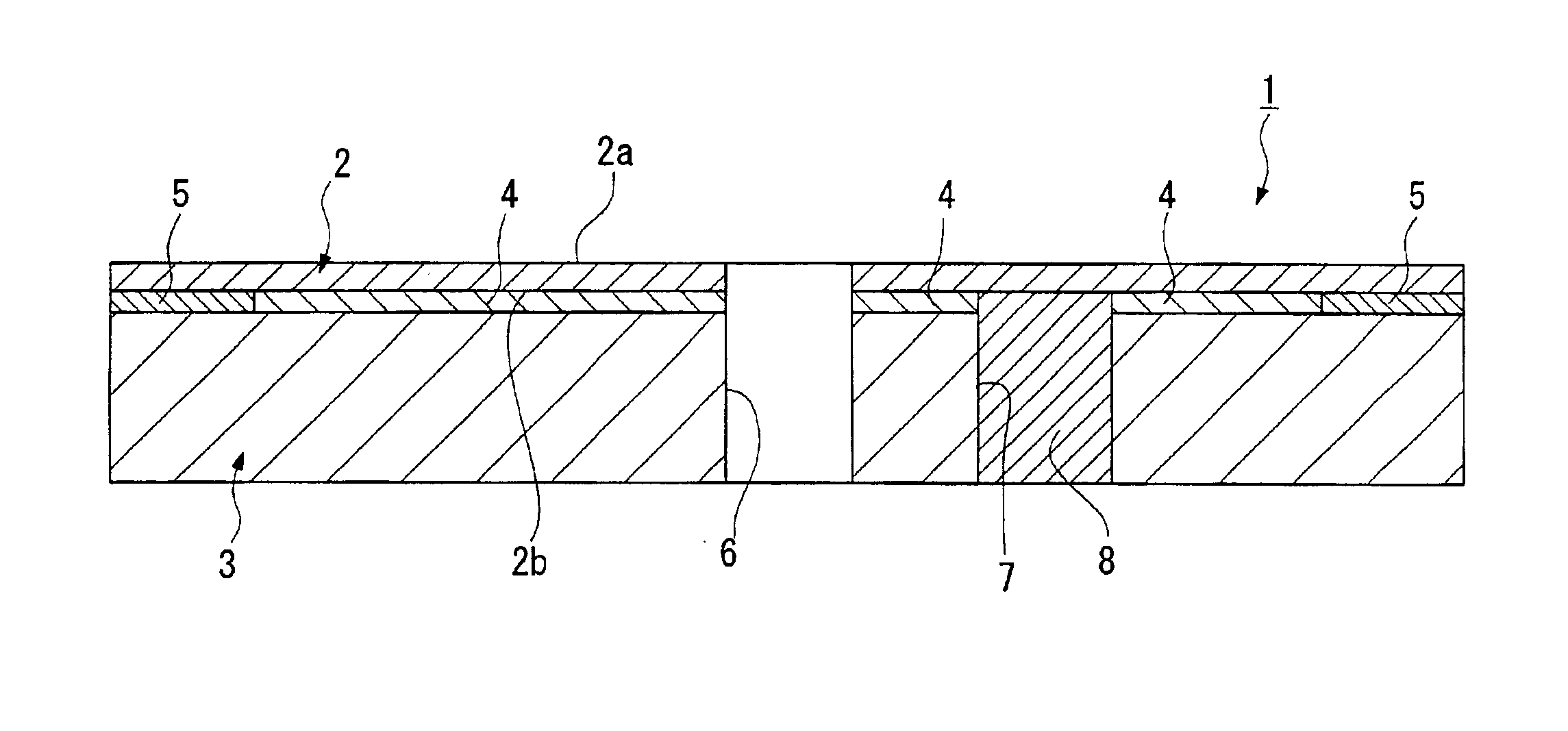
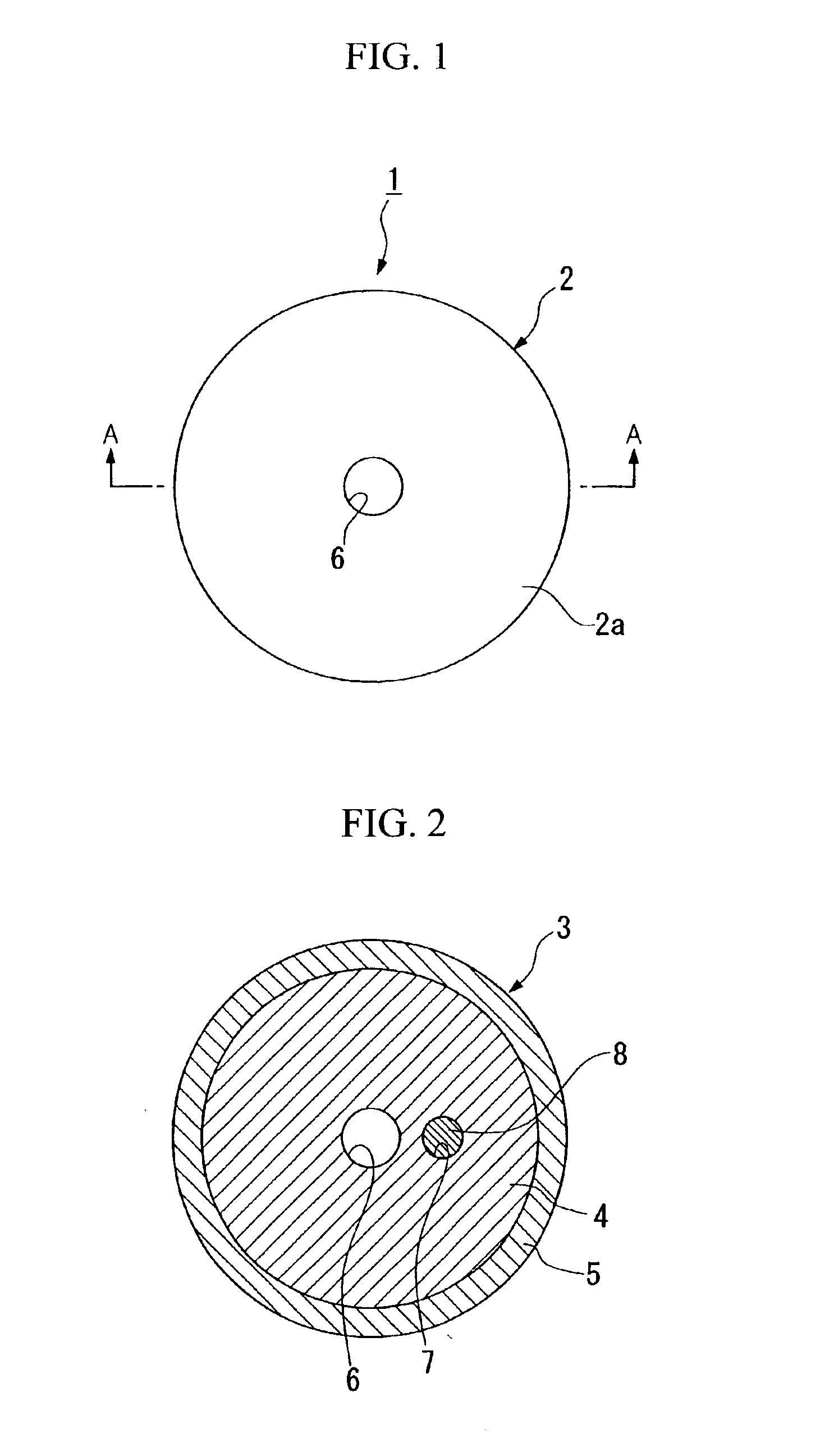
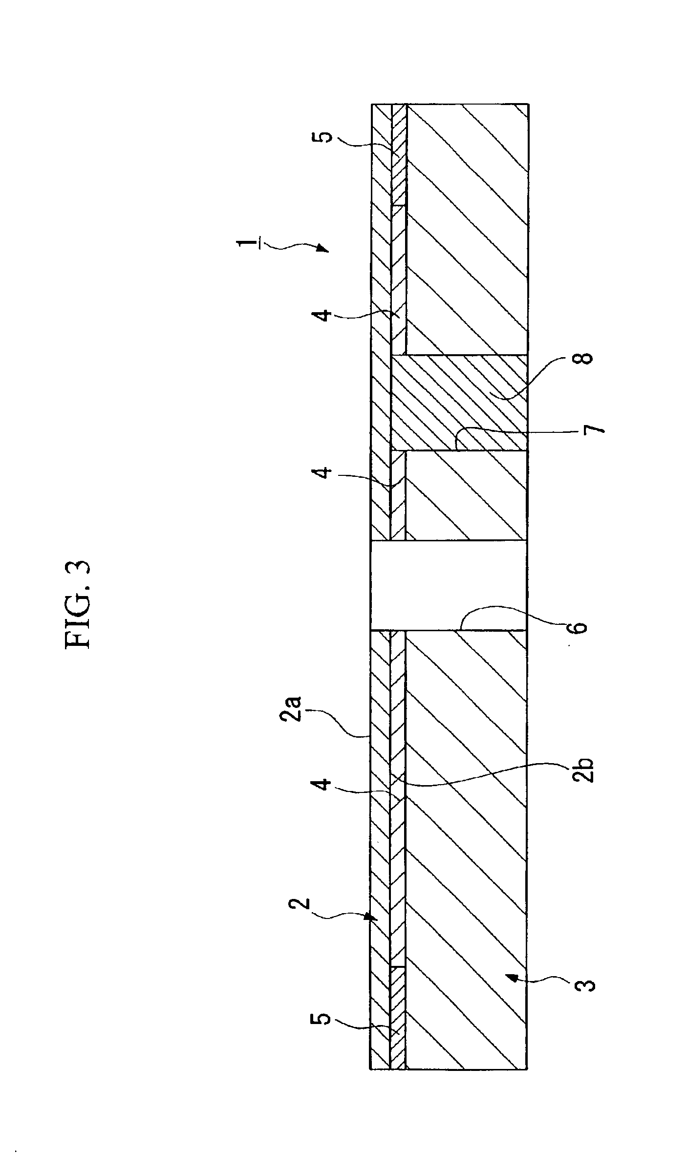
[0041]FIG. 1 is a plan view showing an electrostatic chuck of a first embodiment of the present invention, being an example of a circular electrostatic chuck, FIG. 2 is a lateral cross-sectional view of the same, and FIG. 3 is a cross-sectional view along line A—A of FIG. 1.
[0042]This electrostatic chuck 1 is constructed with, as its main components; a first insulating member 2 whose upper surface (one principal plane) serves as a mounting surface 2a on which is mounted a plate specimen such as a semiconductor wafer, a metal wafer, a glass substrate or the like, a second insulating member 3, which is positioned facing a lower surface (other principal plane) side of the first insulating member 2, and an internal electrode 4 located between the first insulating member 2 and the second insulating member 3.
[0043]The first insulating member 2 and the second insulating member 3 are joined airtightly via the internal electrode 4 and an insulating joining layer 5 provided on a region betwee...
second embodiment
[0088]In an electrostatic chuck of a second embodiment of the present invention, the material composition of the first insulating member 2 constituting the electrostatic chuck 1 is changed from the first embodiment as described above. Points other than this are exactly the same as for the electrostatic chuck 1 of the first embodiment.
[0089]A first insulating member according to the present embodiment is manufactured by a composite ceramic having silicon carbide and aluminum oxide as its main constituents, and on the surface of the silicon carbide particles, a film coating comprising a mullite based material with a thickness of, for example, 0.2 μm or less, and preferably 0.1 μm or less, is formed.
[0090]For the mullite based material, other than mullite (3Al2O3·2SiO2), a solid solution or a glassy composite of aluminum oxide and mullite, or a solid solution or glassy composite of silicon dioxide (SiO2) and mullite is preferable.
[0091]It is desirable that the thickness of this film co...
example 1
[0110]An ultrafine silicon carbide powder whose average particle diameter was 0.05 μm was vapor phase synthesized by using a plasma CVD method, and 3 wt % of the ultrafine silicon carbide powder and 97 wt % of aluminum oxide powder whose average particle diameter was 0.5 μm were mixed for two hours by using a high pressure homogenization apparatus (ULTHIMAIZER SYSTEM™, manufactured by Sugino Machine Limited) pressure: 1.52×10⁸ Pa (1500 atmospheres), thus obtaining a mixed powder.
[0111]After the obtained mixed powder was dried, it was molded into a discoid shape, then calcinated under pressure at a temperature of 1780° C. in an argon (Ar) atmosphere for three hours by using a hot isostatic pressing method (HIP), thereby producing two discoid shaped composite ceramics with a diameter of 195 mm and a thickness of 4 mm. Here, the applied pressure was 30 MPa.
[0112]Next, a through hole with an internal diameter of 5 mm was formed in the central part of one composite ceramic, of the two di...
PUM
| Property | Measurement | Unit |
|---|---|---|
| volume resistivity | aaaaa | aaaaa |
| temperature | aaaaa | aaaaa |
| particle diameter | aaaaa | aaaaa |
Abstract
Description
Claims
Application Information
 - R&D
- Intellectual Property
- Life Sciences
- Materials
- Tech Scout
- Unparalleled Data Quality
- Higher Quality Content
- 60% Fewer Hallucinations
Browse by: Latest US Patents, China's latest patents, Technical Efficacy Thesaurus, Application Domain, Technology Topic, Popular Technical Reports.
© 2025 PatSnap. All rights reserved.Legal|Privacy policy|Modern Slavery Act Transparency Statement|Sitemap|About US| Contact US: help@patsnap.com