Process for producing toner particles

a technology of toner particles and processing equipment, applied in the field of processing, can solve the problems of limiting the range in which toner materials are selected, fine particles tend to be included in the particles in a relatively large proportion, and the kneaded products must be brittle enough, so as to prevent excess power consumption, reduce the effect of dispersibility and good image density

Active Publication Date: 2005-10-04
CANON KK
View PDF19 Cites 14 Cited by
  • Summary
  • Abstract
  • Description
  • Claims
  • Application Information

AI Technical Summary

Benefits of technology

[0020]Another object of the present invention is to provide, in a process for producing toner particles which has the step of dispersing a release agent or a colorant or the both in a liquid medium, a process for producing toner particles by which, restraining excess power consumption and keeping dispersibility from lowering, toner particles in which the colorant stands dispersed more homogeneously and the release agent which is substantially insoluble at normal temperature or within the range of temperature having been controlled during production stands dispersed more homogeneously and which promise good image density and anti-offset properties can be produced in a high efficiency and stably.

Problems solved by technology

Reasonably good toners can be produced by such a production method, but there is a limit to the range in which toner materials are selected.
For example, in the case when the toner particles are produced by pulverization, kneaded products must be brittle enough to be pulverizable by means of economically available production apparatus.
Kneaded products made brittle in order to meet these requirement tend to result in a broad particle size range of the particles formed when actually pulverized at a high speed, especially causing a problem that fine particles tend to be included in the particles in a relatively large proportion.
Moreover, toners making use of such highly brittle materials tend to be further pulverized or powdered when used in, e.g., copying machines.
In this pulverization method, it is also not easy to uniformly disperse solid fine particles of colorants or the like in the resin, and, depending on the degree of their dispersion, toners may cause an increase in fog, a decrease in image density and a lowering of color mixing properties or transparency when images are formed.
Also, colorants may come bare to surfaces of toner particles to cause fluctuations in developing performance of toners.
However, in such an agitation media type dispersion machine, the particles of colorant or the particles of release agent are dispersed or crushed by the aid of their collision against media and shear stress between them, and hence kinetic energy must be applied to the media by agitation.
This energy is so large as to cause a rise in production cost for toner particles.
This generation of heat may adversely affect the polymerizable monomer, e.g., make it undergo thermal polymerization.
Excess heat generation caused by agitation results in wasteful use of energy.
This, however, has caused a problem that the agitation power increases correspondingly.
In addition, friction tends to be produced between the media and the machine casing surface with which the former comes into contact, bringing about a possibility that wear dust contaminates toner particles more frequently.
Without using such an agitation media type dispersion machine consuming a large power (electric power), a medialess dispersion machine (a dispersion machine commonly called a colloid mill) may also be used to restrain excess power consumption, but it has not been easy to achieve the desired dispersion.
Taking account of shaft run-out of the rotating shaft and its mechanical precision, it is difficult to narrow the gap more than this.
However, toners for electrophotography have particle diameters of 3 to 15 μm, and the shear force produced at the gap that is hundreds of times to thousands of times the particle diameters is not enough to effect sufficient continuous granulation, to cause short pass or shortage of shear force, making it difficult to achieve the desired toner particle diameter and particle size distribution.

Method used


Image

  • Process for producing toner particles
  • Process for producing toner particles
  • Process for producing toner particles

Examples


example 1

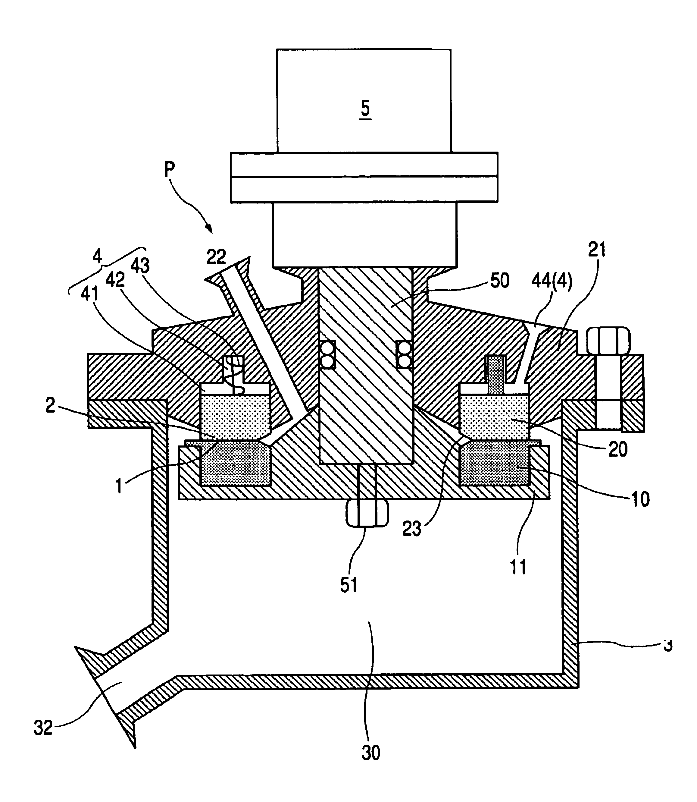
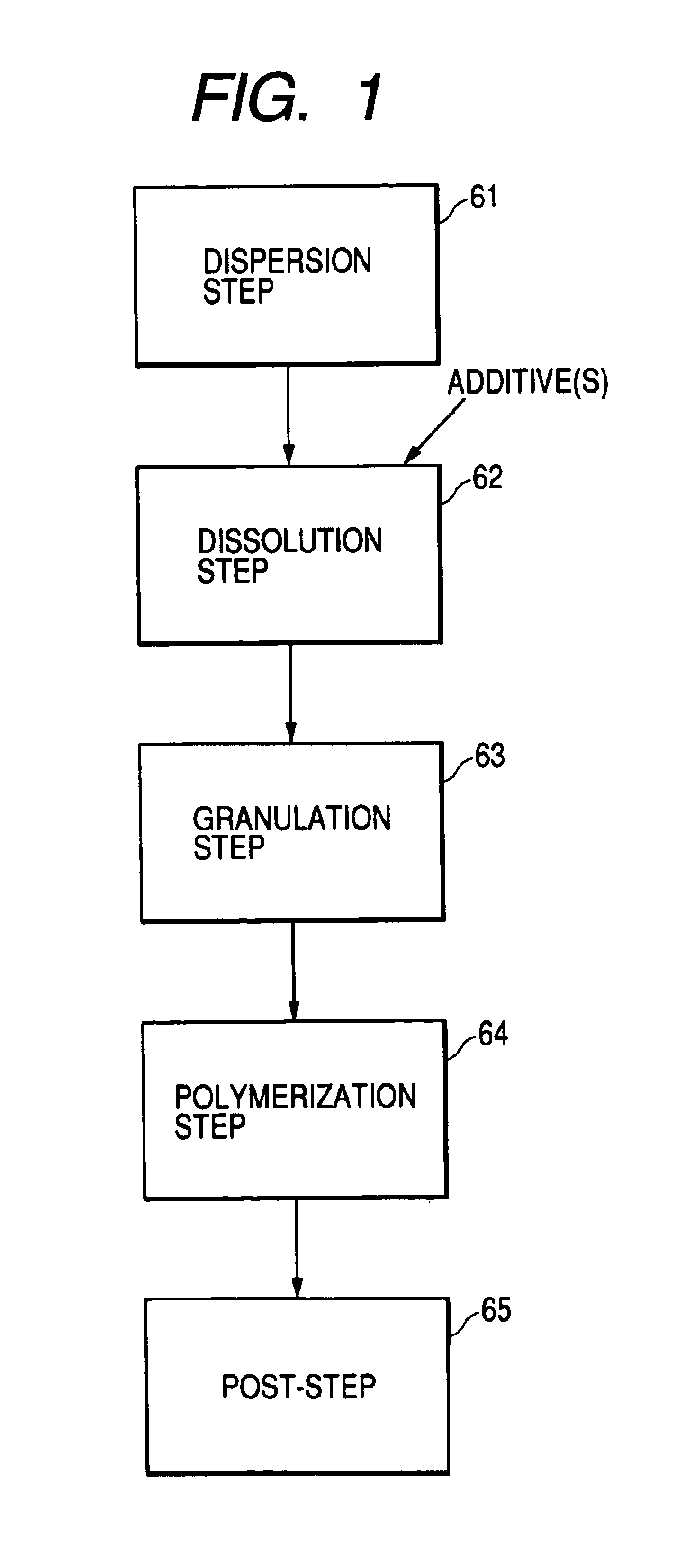
[0204]The apparatus shown in FIGS. 5 and 6 (diameter of the first treatment ring 10: 100 mm) was used as the fine-dispersion machine in the dispersion step 61 shown in FIG. 1, and the step of dispersing a colorant was carried out.

[0205]First, 60 parts by weight of a styrene monomer, 8 parts by weight of a magenta colorant (C.I. Pigment Red 122) and 1 part by weight of a negative charge control agent (a salicylic-acid aluminum compound E-88, available from Orient Chemical Industries, Ltd.) were put into a container made ready for use, followed by pre-dispersion by means of THREEONE-MOTOR to prepare a first fluid mixture (first polymerizable-monomer fluid mixture).

[0206]Next, the first treatment ring 10 shown in FIGS. 5 and 6 was rotated at a number of revolutions set to 8,000 rpm. Compressed air of 600 kPa was introduced through the air feed port 44 to regulate the surface pressure between the first treatment ring 10 and the second treatment ring 20. Thereafter, the first fluid mixtu...

example 2

[0207]A second fluid mixture (second polymerizable-monomer fluid mixture) in which the colorant stood finely dispersed was obtained in the same manner as in Example 1 except that the number of revolutions of the first treatment ring 10 was set to 10,000 rpm and compressed air of 700 kPa was introduced through the air feed port 44. Here, the electric power of the rotary derive unit 5 was measured to find that it was 2.5 kW. The value of glossiness and volume-average particle diameter of the second polymerizable-monomer fluid mixture obtained were measured to find that they were 48% and 0.07 μm, respectively. This second fluid mixture was prepared instantaneously within few seconds. To prepare this second fluid mixture, a power of 0.21 kWh / kg was necessary per unit weight.

example 3

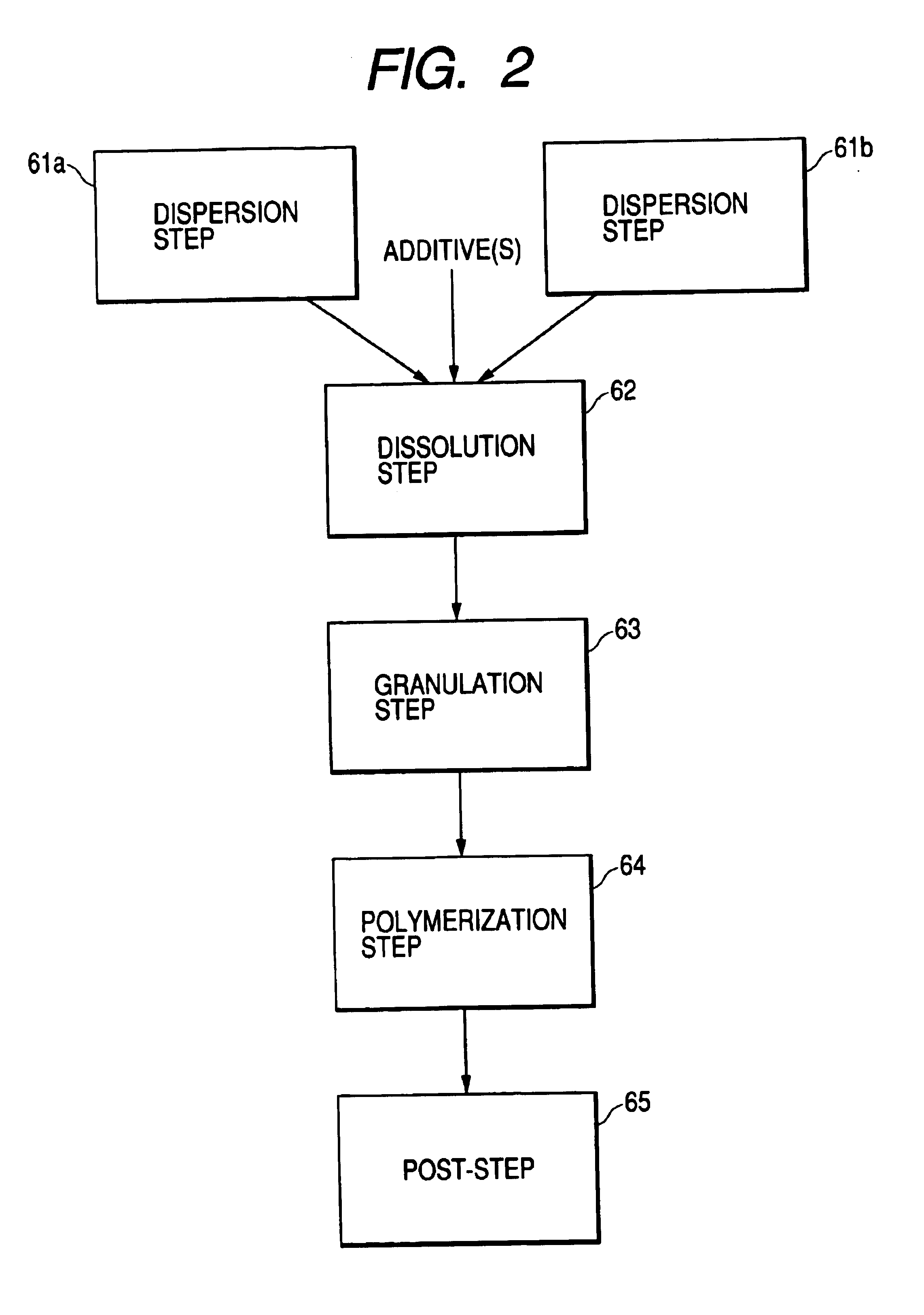
[0209]The apparatus shown in FIGS. 5 and 6 (diameter of the first treatment ring 10: 100 mm) was used as the fine-dispersion machine in the dispersion step 61a shown in FIG. 2, and the step of dispersing a release agent was carried out.

[0210]First, 30 parts by weight of a styrene monomer, 3.5 parts by weight of a release agent (low-molecular-weight polyethylene wax PW850, available from Toyo Petroleum Co.; melting point: 105° C.) were put into a container made ready for use, followed by pre-dispersion by means of THREEONE-MOTOR to prepare a first fluid mixture (first polymerizable-monomer fluid mixture).

[0211]Next, the first treatment ring 10 shown in FIGS. 5 and 6 was rotated at a number of revolutions set to 8,000 rpm. Compressed air of 600 kPa was introduced through the air feed port 44 to regulate the surface pressure between the first treatment ring 10 and the second treatment ring 20. Thereafter, the first fluid mixture was introduced into the fine-dispersion machine from the ...


PUM


Abstract

In a process for producing toner particles by pre-dispersing at least a colorant and/or a release agent in a first dispersion medium to prepare a first fluid mixture, preparing a second fluid mixture from the first fluid mixture by means of a fine-dispersion machine, and forming toner particles from the second fluid mixture;
    • (i) the fine-dispersion machine has at least a first treatment ring and a second treatment ring approachable to and separable from the former and a rotary drive mechanism which makes the former rotate relatively to the latter, and (ii) the first fluid mixture is introduced to the part between the first treatment ring and the second treatment ring to make the latter separate from the former, and the colorant and/or the release agent are dispersed in the form of fine particles by the rotation of the first treatment ring to obtain the second fluid mixture.

Description

BACKGROUND OF THE INVENTION[0001]1. Field of the Invention[0002]This invention relates to a process for producing toner particles having superior electrophotographic performance in each particle of which a colorant and a release agent or a mixture of these stand(s) dispersed finely and uniformly. This invention also relates to a process by which the toner particles having superior electrophotographic performance in each particle of which a colorant and a release agent or a mixture of these stand(s) dispersed finely and uniformly are produced controlling any excess power consumption.[0003]This invention still also relates to a process by which toner particles containing no coarse particles and having sharp particle size distribution are obtained in a high efficiency.[0004]2. Related Background Art[0005]Conventionally, electrophotography is a process in which fixed images are obtained by forming an electrostatic latent image on a photosensitive member by various means, subsequently de...

Claims


Application Information

Patent Timeline
Patent Type & Authority Patents(United States)
IPC IPC(8): G03G9/08
CPCG03G9/0804
Inventor TSUJI, YOSHINORIFUMITA, HIDEKAZU
Owner CANON KK
Why Eureka
Try Eureka