
Cold cathode and cold cathode discharge device

a discharge device and cold cathode technology, which is applied in the manufacture of electric discharge tubes/lamps, discharge tubes luminescnet screens, electrode systems, etc., can solve the problems of difficult exchanging lamps, inferior conversion efficiency of cold cathode discharge lamps to thermal cathode discharge lamps, etc., and achieve long life and high efficiency

Inactive Publication Date: 2005-10-04
KK TOSHIBA
View PDF15 Cites 19 Cited by
  • Summary
  • Abstract
  • Description
  • Claims
  • Application Information

AI Technical Summary

Benefits of technology

[0007]Accordingly, the present invention is intended to solve the two problems i.e. light emitting efficiency and life of the cold cathode discharge device, and consequently to realize both higher efficiency of light emission and longer life of the device.
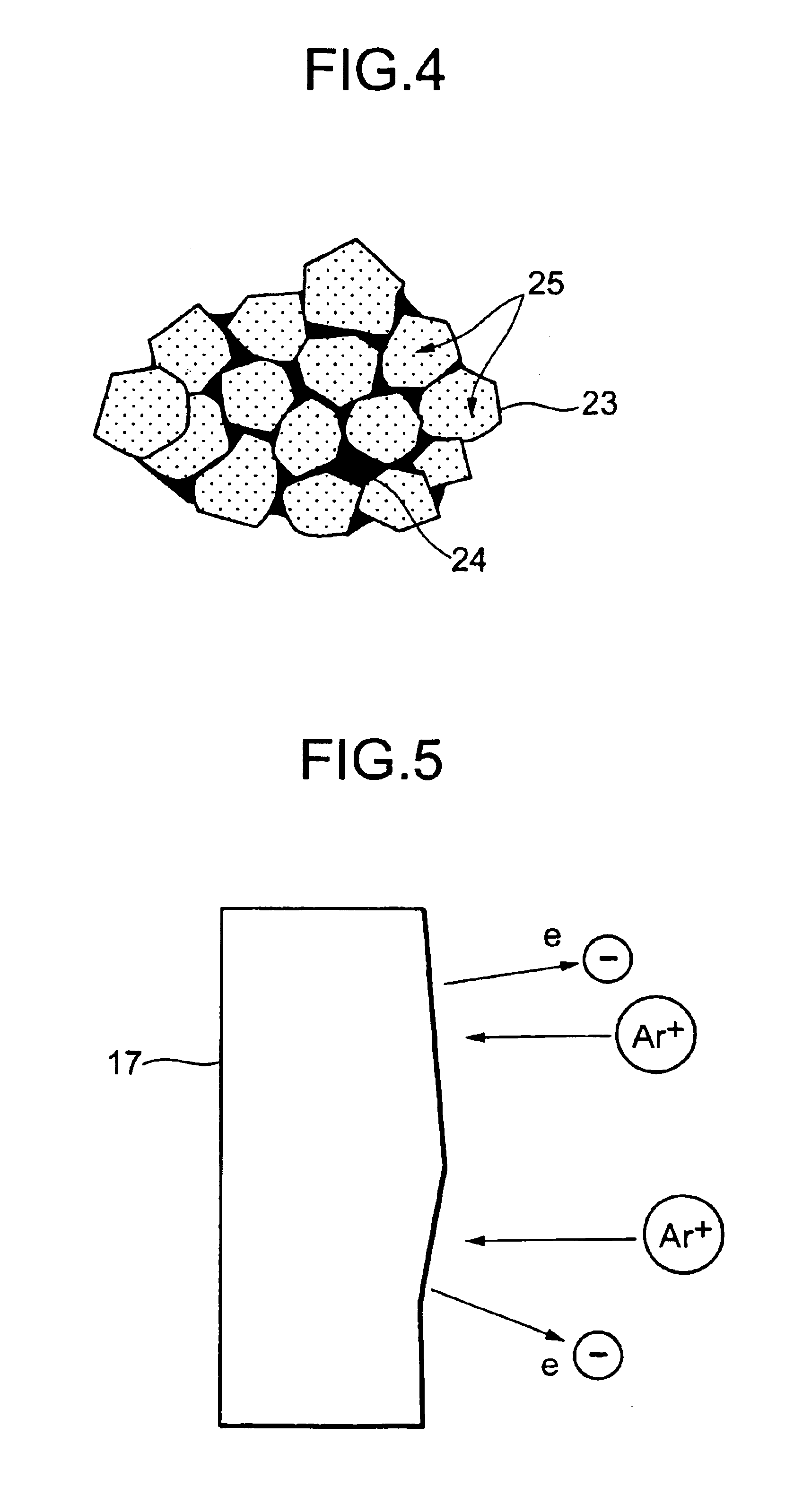
[0015]The cold cathode according to the present invention employs a carbon system electrode comprising diamond phase and graphite or amorphous carbon layer instead of a metallic electrode of such as nickel (Ni),which is used for conventional cold cathodes. Carbon is contained within the inside of the discharge tube together with mercury, so as to play a role to assist mercury to be excited effectively. Carbon is one of the elements that are the hardest of almost all elements with respect to spattering by argon (Ar) ion bombardment. On the other hand, life of the cold cathode discharge lamp finally depends on wear-off of the electrode by spattering, so that the carbon system material is very effective against such phenomenon.
[0017]The present invention makes efficiency of the secondary electron emission be consistent with the anti-spattering property by combining the diamond with the graphite system, resulting in realization of the cold cathode discharge device that has high efficiency and long life.

Problems solved by technology

While the lamp is turned on, it is therefore necessary to supply a high voltage thereto, and consequently the cold cathode discharge lamp is inferior to the thermal cathode discharge lamp with regard to the conversion efficiency of electric power into light, because of the high electric field and the high voltage mentioned above.
However the cold cathode type lasts longer than the thermal cathode type, so that it is frequently used for some applications where exchanging the lamp is not easy.

Method used


Image

  • Cold cathode and cold cathode discharge device
  • Cold cathode and cold cathode discharge device
  • Cold cathode and cold cathode discharge device

Examples


first embodiment

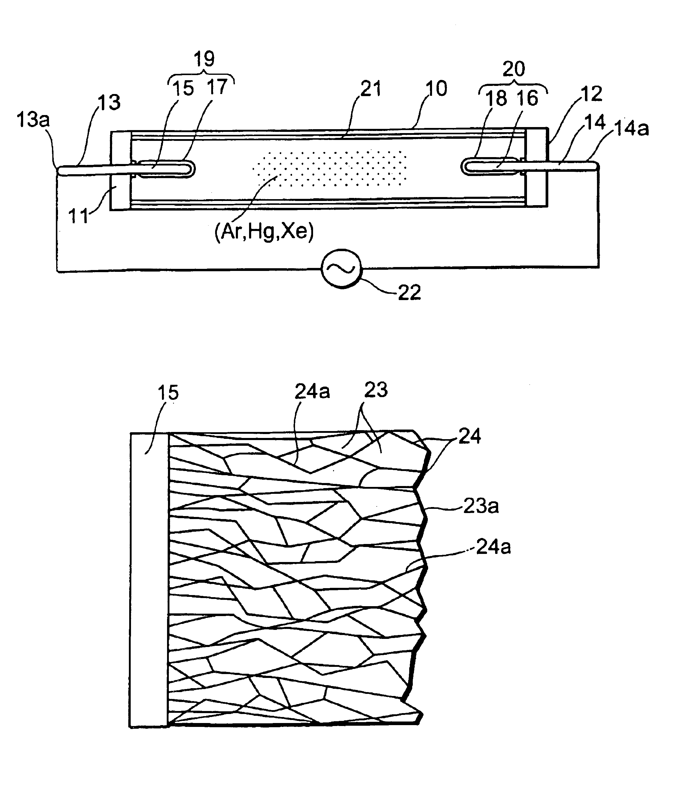
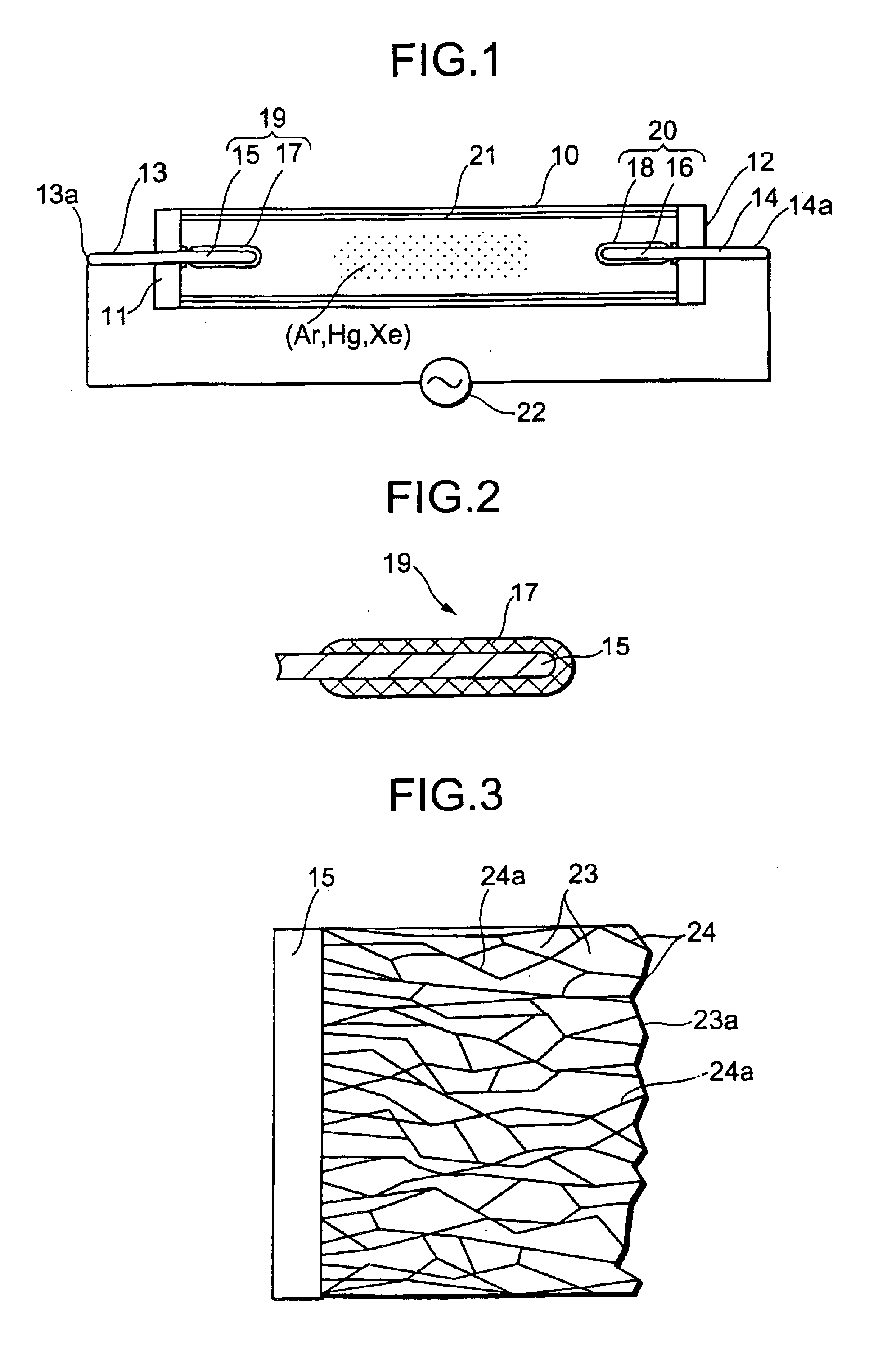
[0029]FIG. 1 and FIG. 2 show the present invention, in which both ends of an elongated envelope 10 of transparent glass are formed with stems 11 and 12 where leads 13 and 14 are hermetically sealed respectively. The portions of the leads, which protrude inside the envelope, are cathode-supporting members 15 and 16 of metal such as nickel. Electron emitters 17 and 18 are stuck to the supporting members and constitute cold cathodes 19 and 20 together with the supporting members. A fluorescent film 21 is coated on the inner surface of the envelope, and the envelope is filled with a discharge gas of Ar, Hg and Xe at a low pressure.

[0030]Lead portions 13a and 14a protruding out of the envelope toward the outside are electrode terminals connected to, for example, an AC power source 22. When a voltage is applied thereto, discharge starts in the envelope., one of the electrodes, for example, 17 emitting electrons as a cold cathode and the other electrode, for example, 18 acting as an anode....

second embodiment

[0037]FIG. 8 and FIG. 9 show the present invention. Each part denoted by the same mark as that in FIG. 1 is the same part. The both ends of a tubular envelope 10 of transparent quartz or glass are sealed with stems 11 and 12 through which leads 13 and 14 penetrate hermetically. The portions of the leads protruding inside the envelope are connected with substrates 30 and 31 for the cathode supporting members of metal such as nickel. Layered electron emitters 32 and 33 are formed on the surfaces of the supporting members 30 and 31 so as to construct cold cathodes 34 and 35. A fluorescent film 20 is coated on the inner surface of the envelope, which is filled with a discharge gas of Ar, Hg and Xe at a low pressure. Furthermore, the filled gas may be selected from other rare gases such as neon (Ne).

[0038]The electron emitter 32(or 33) is formed as a diamond system layer on the supporting member substrate 30(or 31). The structure reduces volume of the electrode and can make the manufactu...

third embodiment

[0046]FIG. 10 shows the present invention. The electron emitter 40, which is a mixed phase of diamond phase and amorphous carbon phase, has a lowered resistance and mechanical strength that can support it by itself, so that most portion of the cold cathode can be formed by the electron emitter 40 as shown in the figure and the supporting member can support a part of the emitter to prepare the cold cathode. Therefore, the emitter can withstand wear-out of the electrode, even if it is used for a tiny electrode of a miniaturized discharge lamp. This is advantageous for the lamp to have long life.

[0047]As explained by the above embodiments, first of all, improving the efficiency of light emission, which is the problem for the cold cathode discharge lamp, can be achieved according to the present invention, because the diamond has a high efficiency of secondary electron emission thanks to the energy band structure thereof as mentioned above. Especially, efficiency of electron emission can...


PUM


Abstract

A cold cathode discharge device with high efficiency of light emission and long life is prepared by a cold cathode having both high secondary electron emission and anti-spattering property.Using carbon system cold cathodes constituted of a mixed phase of diamond and graphite, a cold cathode discharge device with high efficiency of light emission and long life is realized. It is desirable that an element having a wavelength of light emission equal to or shorter than 200 nanometers should be mixed in the discharge gas.

Description

CROSS-REFERENCE TO RELATED APPLICATIONS[0001]This application is a Divisional of U.S. patent application Ser. No. 10 / 098,571, filed on Mar. 18, 2002 now U.S. Pat. No. 6,781,294, and is based upon and claims the benefit of priority from the prior Japanese Patent Application No. 2001-97416, filed on Mar. 29, 2001, the entire contents of which are incorporated herein by reference.BACKGROUND OF THE INVENTION[0002]1. Field of the Invention[0003]This invention relates to a cold cathode and a cold cathode discharge device.[0004]2. Description of the Related Art[0005]A cold cathode discharge device represented by a cold cathode discharge lamp has a simple structure, which does not employ any heating filaments. Accordingly, because the device can easily be miniaturized and operate at a low temperature, and moreover has a relatively long life, it is widely put to use recently for a wide variety of lighting or a backlight of a liquid crystal display device.[0006]On the other hand, because the ...

Claims


Application Information

Patent Timeline
IPC IPC(8): H01J61/067H01J1/30H01J61/16
CPCH01J61/0677H01J1/30
Inventor SAKAI, TADASHIONO, TOMIOSAKUMA, NAOSHILI, ZHANG
Owner KK TOSHIBA
Learn More