Method and arrangement for reducing frequency offset in a radio receiver

Inactive Publication Date: 2005-10-18
NOKIA TECHNOLOGLES OY
View PDF8 Cites 15 Cited by
  • Summary
  • Abstract
  • Description
  • Claims
  • Application Information

AI Technical Summary

Benefits of technology

[0016]The principle of the invention is next described referring to FIGS. 2a and 2b.
[0017]In the channel, as seen by the baseband receiver, the transmitted signal x(t) is multiplied with c(t) and additive white gaussian noise (AWGN) n(t) is added to it:
[0018]Due to the multiplication with a complex phasor the center frequency of the received, downconverted signal is moved by the amount of fe. The spectrum of c(t). 296-299, is illustrated in FIG. 2b. fD is called (maximum) Doppler frequency and it depends on the mobile speed and is defined as fD=v⁢ ⁢f0c(3)
[0019]The frequency offset is detected from the consecutive filtered complex channel estimates. For example, the phase difference between to consecutive channel estimates is measured in a phase analyzer block and a differentiator after it. In case of a feedback compensation, the estim

Problems solved by technology

However, it is generally not possible to compensate RACH (Random Access CHannel) bur

Method used


Image

  • Method and arrangement for reducing frequency offset in a radio receiver
  • Method and arrangement for reducing frequency offset in a radio receiver
  • Method and arrangement for reducing frequency offset in a radio receiver

Examples


first embodiment

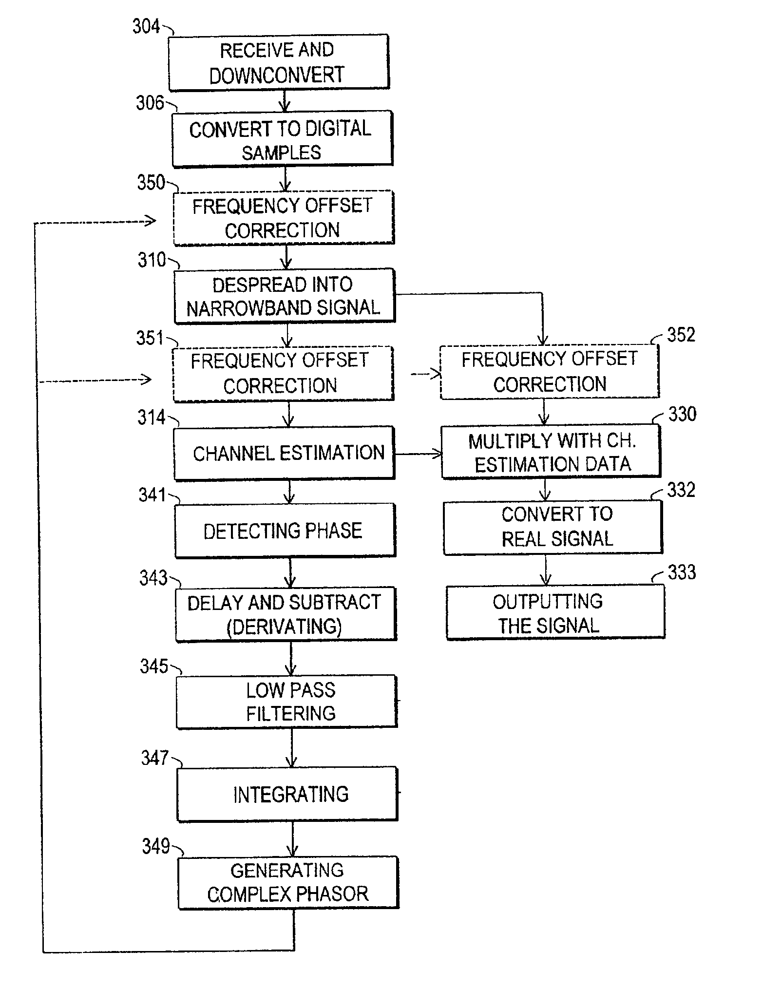
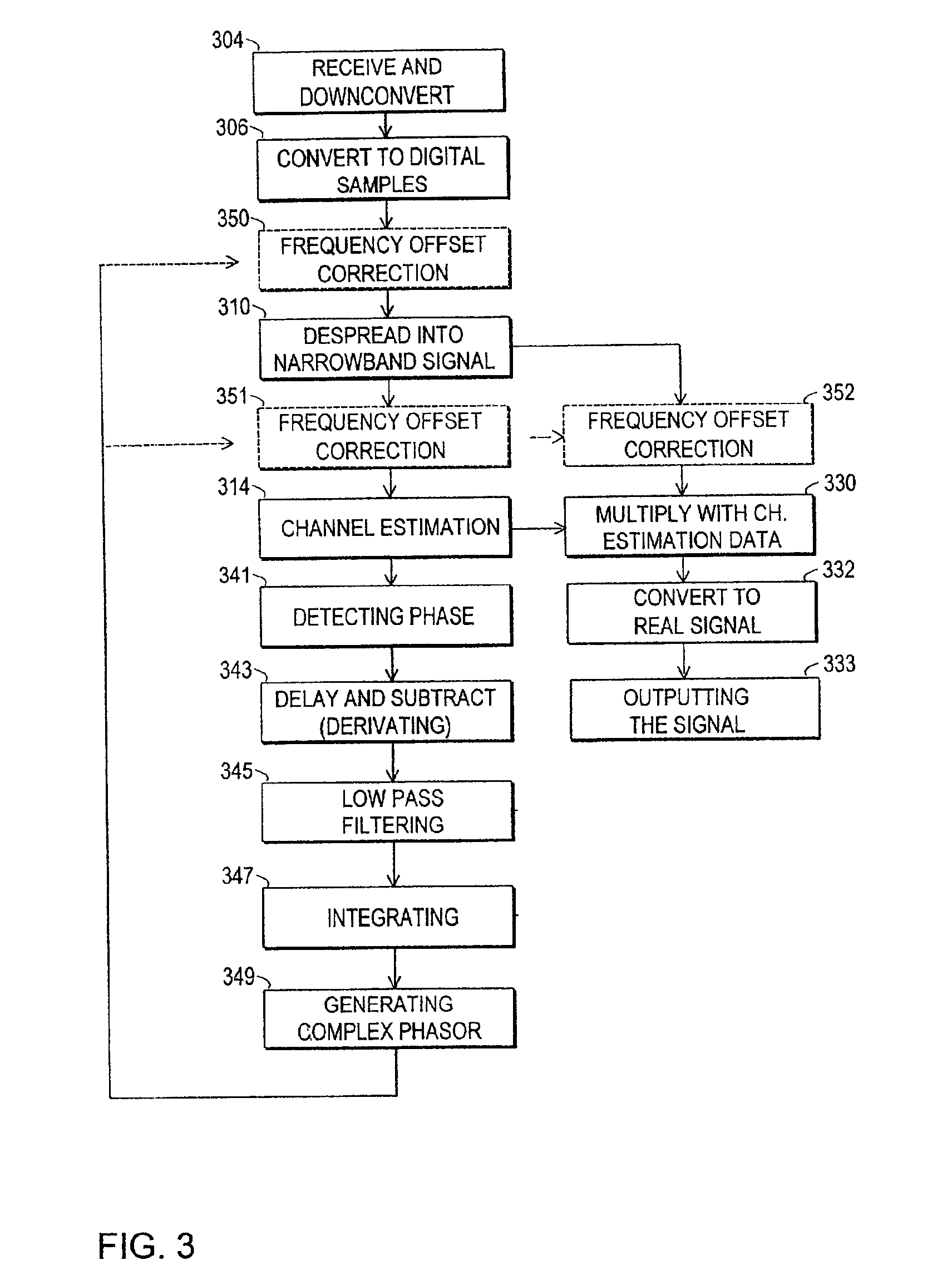
[0075]FIG. 3 illustrates a flow diagram of a receiving method according to the invention where frequency offset correction is performed with a feedback signal. A received RF signal is first downconverted to the baseband by mixing with a local oscillator (LO) signal, 304, and then converted to digital samples forming a digital baseband signal, 306. If the frequency offset correction is performed to the wideband signal, the signal is then multiplied with a complex phasor in step 350.

[0076]The signal is further despread to form a narrowband signal. 310. The despreading is performed with a long code successively with a long code and a short code. If the frequency offset correction is performed to the narrowband signal, then the signal after despreading with a long code is multiplied with the complex phasor in step 351, and the signal which is despread with both the long code and the short code is multiplied with the complex phasor in step 352.

[0077]A channel estimate is formed based on ...

second embodiment

[0087]FIG. 6 illustrates an arrangement according to the invention where feedback correction of the frequency offset is made for a narrowband signal. Corresponding to the arrangement of FIG. 5, it comprises blocks for multiplying the baseband signal with the appropriate long code 610 and the appropriate short code 620, summing blocks 612 and 622 in the two signal branches, channel estimator 614, a multiplier 630 for multiplying the signals from the two branches and a converter 632 for forming a real signal from the output of the multiplier 630.

[0088]The arrangement of FIG. 6 also comprises a feedback branch with a phase detector 641, a derivator 642, 643, a low pass filter 645, an integrator 647 and a complex phasor generator 649 for forming a complex phasor for the frequency offset compensation.

[0089]In the arrangement of FIG. 6 the compensation with the complex phasor is, however, applied to the narrowband signal after despreading. The arrangement therefore comprises two multiplie...


PUM


Abstract

The invention concerns generally the technology of reducing frequency offset in a radio receiver. Especially the invention concerns receivers where a channel estimator is used for correcting the base band signal. The objects of the invention are achieved by monitoring the phase of the channel estimation output and generating a complex phasor on the basis of successive phase values. The received baseband signal is then multiplied by the generated complex phasor for compensating the frequency offset. The frequency compensation can be made before or after said channel estimation thus producing a feedback compensation or feed forward compensation. The feedback compensation can be implemented by compensating the baseband signal either prior to the despreading or after the despreading.

Description

TECHNICAL FIELD OF THE INVENTION[0001]The invention relates generally to the technology of reducing frequency offset in a radio receiver. Especially the invention concerns receivers where a channel estimator is used for correcting the signal e.g. due to the multipath transmission. The invention is preferably applied in receivers of mobile communication systems, especially in systems that are based on CDMA (Code Division Multiple Access).BACKGROUND ART OF THE INVENTION[0002]A received radio signal has often been corrupted by noise and intersymbol interference caused by e.g. multipath propagation. The multipath propagation may be e.g. of a Rician type where there is one (direct) path with a strong received signal, and other (reflected) paths with smaller signal strength. The Rician type propagation is usual in satellite systems. Another type of multipath propagation is a Rayleigh fading channel, where the strength of the received signals from different paths are of the similar magnitu...

Claims


Application Information

Patent Timeline
IPC IPC(8): H03J7/00H04L27/38H04B1/707
CPCH03J7/00H04B1/707
Inventor VIHRIALA, JAAKKO
Owner NOKIA TECHNOLOGLES OY
Why Eureka
Try Eureka