Lithographic apparatus and device manufacturing method

a technology of lithographic apparatus and manufacturing method, applied in the field of lithographic apparatus, can solve the problems of complex illumination system, inconvenient contamination of importance, and achieve the effect of simple measurement of angular intensity distribution, simple illumination system, and simple manufacturing method

Inactive Publication Date: 2005-10-25
ASML NETHERLANDS BV
View PDF6 Cites 88 Cited by
  • Summary
  • Abstract
  • Description
  • Claims
  • Application Information

AI Technical Summary

Benefits of technology

[0025]It is an aspect of embodiments of the present invention to make it possible to obtain information a...

Problems solved by technology

Very complex illumination systems are to ensure realization of the desired intensity distributions.
Also erratic factors, such as contamination may be of importance.
Measurement of the angular intensity distribution is less straightforward.
Measurement of position dependent intensity at a pupil plane currently involves an interru...

Method used


Image

  • Lithographic apparatus and device manufacturing method
  • Lithographic apparatus and device manufacturing method
  • Lithographic apparatus and device manufacturing method

Examples


embodiment 1

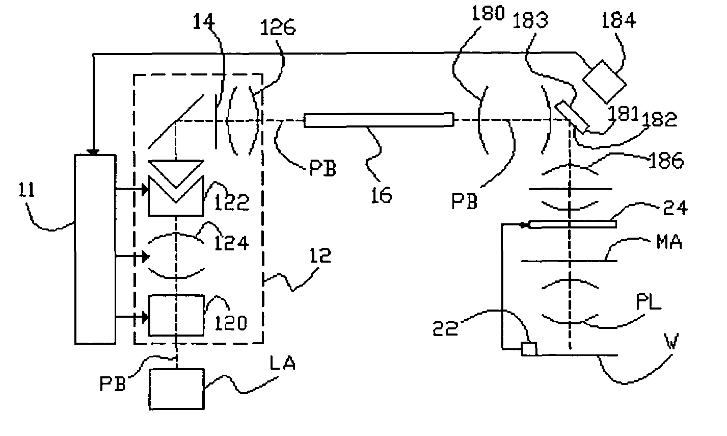
[0043]FIG. 1 schematically depicts a lithographic apparatus according to a particular embodiment of the invention. The apparatus comprises:

[0044]a radiation system Ex, IL, for supplying a projection beam PB of radiation (e.g., ultraviolet radiation). In this particular case, the radiation system also comprises a radiation source LA;

[0045]a first object table (mask table) MT provided with a mask holder for holding a mask MA (e.g., a reticle);

[0046]a second object table (substrate table) WT provided with a substrate holder for holding a substrate W (e.g., a resist-coated silicon wafer); and

[0047]a projection system (“lens”) PL (e.g., a refractive, reflective or catadioptric lens) for imaging an irradiated portion of the mask MA onto a target portion C (e.g., comprising one or more dies) of the substrate W.

[0048]As here depicted, the apparatus is of a transmissive type (i.e., has a transmissive mask). However, in general, it may also be of a reflective type, for example, with a reflect...


PUM


Abstract

In a lithographic apparatus the angle dependence of the intensity distribution of a projection beam at a substrate is controlled. A beam splitter is located in the beam near a pupil plane. The beam splitter splits off an auxiliary beam, which is used to measure information about the spatial intensity distribution of the beam at the pupil plane. The measured position dependence in the auxiliary beam may be decontrolled using boundary conditions inherent to the illuminator to compensate for offset between the pupil plane and a detection element. The measured position dependence may be used to control parameters of an optical element that manipulates the position dependence in the pupil plane. An example of such an optical element is a matrix of elements that controllably steer the direction of parts of the beam. Thus a continuous feedback loop may be realized.

Description

BACKGROUND OF THE INVENTION[0001]This application claims priority from European Patent Application Nos. 02080031.4, filed Dec. 2, 2002 and 03076401.3, filed May 9, 2003, which are herein incorporated by reference in their entirety.[0002]1. Field of the Invention[0003]The present invention generally relates to a lithographic apparatus and more particularly to a lithographic apparatus having an adjustable position dependent intensity distribution.[0004]2. Description of Related Art[0005]The term “patterning means” or “patterning structure” as here employed should be broadly interpreted as referring to structure that can be used to endow an incoming radiation beam with a patterned cross-section, corresponding to a pattern that is to be created in a target portion of the substrate; the term “light valve” can also be used in this context. Generally, said pattern will correspond to a particular functional layer in a device being created in the target portion, such as an integrated circuit...

Claims


Application Information

Patent Timeline
IPC IPC(8): G03F7/20H01L21/027
CPCG03F7/70108G03F7/7085G03F7/70133G03F7/20
Inventor MULDER, HEINE MELLEHOEGEE, JANKOOLEN, ARMAND EUGENE ALBERT
Owner ASML NETHERLANDS BV
Why Eureka
Try Eureka