Flux guide type device, head having the same, and drive

a technology of flux guide and head, applied in the field of magnetic device, can solve the problems of deteriorating resolution in the direction of track width, hindering the implementation of read head, and difficult implementation of highly sensitive tmr head, so as to reduce the attenuation of signal magnetization, reduce the attenuation of signal flux, and effectively miniaturize the device

Inactive Publication Date: 2005-11-01
FUJITSU LTD
View PDF6 Cites 10 Cited by
  • Summary
  • Abstract
  • Description
  • Claims
  • Application Information

AI Technical Summary

Benefits of technology

[0017]The two ferromagnetic layers in each of the flux guide and the second ferromagnetic layer may have different thicknesses in a layer direction, and a difference in layer thickness between the two ferromagnetic layers in the flux guide may be greater than that between the two ferromagnetic layers in the second ferromagnetic layer. This structure may decrease the attenuation of the signal flux from the flux guide to the second ferromagnetic layer.
[0018]A flux guide type device of another aspect of the present invention includes a magnetoresistive device for reading a signal flux, the magnetoresistive device including a first ferromagnetic layer with a substantially fixed direction of magnetization, and a second ferromagnetic layer wit

Problems solved by technology

This is because a read head excessively large for a record bit size would simultaneously take in magnetic information from both a target record track and track(s) adjacent to the target record track, deteriorating resolution in a direction of track's width.
Reading of magnetic information on a track that has been recorded with the surface recording density of the 100 Gbit/in2 would require a read core width with a size of 0.1 μm or less, and this very precise process accuracy is one cause that hinders an implementation of the read head.
Since an available curre

Method used


Image

  • Flux guide type device, head having the same, and drive
  • Flux guide type device, head having the same, and drive
  • Flux guide type device, head having the same, and drive

Examples


example 1

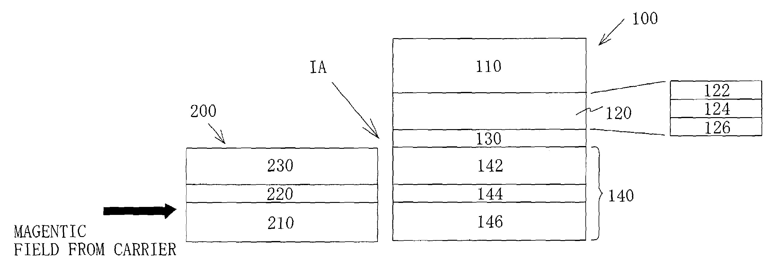
[0086]The structure shown in FIG. 6 is produced. The flux guide film 200 includes a magnetic layer 210 made of CoFe with a thickness of 30 Å, an intermediate layer 220 made of Ru with a thickness of 8 Å, and a magnetic layer 230 made of CoFe with a thickness of 20 Å. At the opposite side to the carrier with respect to the flux guide film 200, the spin-valve film 100 is formed which includes a free magnetic layer 146 made of CoFe with a thickness of 25 Å, a free intermediate layer 144 made of Ru with a thickness of 8 Å, a free magnetic layer 142 made of CoFe with a thickness of 20 Å, a spin-valve intermediate layer 130 made of Cu with a thickness of 25 Å, a pinned magnetic layer 120 made of CoFe with a thickness of 25 Å, and an antiferromagnetic layer 110 made of PdPtMn with a thickness of 150 Å.

[0087]Following a formation of each film, a thermal treatment was conducted to order the PdPtMn exchange-coupling layer, in a vacuum magnetic field at 280° C. for three hours under magnetic-f...

example 2

[0089]The structure shown in FIG. 6 is produced. The flux guide film 200A includes a magnetic layer 210A made of CoFe with a thickness of 25 Å, an intermediate layer 220A made of Ru with a thickness of 8 Å, and a magnetic layer 230A made of CoFe with a thickness of 20 Å. The TMR film 100A is formed on the flux guide film 200A which includes a free magnetic layer 146 made of CoFe with a thickness of 25 Å, a free intermediate layer 144 made of Ru with a thickness of 8 Å, a free magnetic layer 142 made of CoFe with a thickness of 25 Å, a TMR intermediate layer 150 made of Al2O3 with a thickness of 8 Å, a pinned magnetic layer 120 made of CoFe with a thickness of 25 Å, and an antiferromagnetic layer 110 made of PdPtMn with a thickness of 150 Å.

example 3

[0090]The structure shown in FIG. 7 is produced. The TMR film 100B is formed which includes a free magnetic layer 146B made of CoFe with a thickness of 23 Å, a free intermediate layer 144B made of Ru with a thickness of 8 Å, a free magnetic layer 142B made of CoFe with a thickness of 25 Å, a TMR intermediate layer 150 made of Al2O3 with a thickness of 8 Å, a pinned magnetic layer 120 made of CoFe with a thickness of 25 Å, and an antiferromagnetic layer 110 made of PdPtMn with a thickness of 150 Å. The process then applies resist onto part which will become the TMR device 100B, and removes through etching a portion from the top to the Al2O3 film, thereby projecting the free layer 140B and activating the flux guide film 200B.

[0091]FIG. 10 shows the flux guide type head manufactured in accordance with this method. The lower electrode layer 52b is formed with a thickness of 200 Å on the lower shield 52a made of NiFe with a thickness of 3 μm. The TMR device 100B is formed in accordance w...


PUM

PropertyMeasurementUnit
Thicknessaaaaaaaaaa
Thicknessaaaaaaaaaa
Nanoscale particle sizeaaaaaaaaaa

Abstract

A flux guide type includes a magnetoresistive device for reading a signal flux, and a flux guide for transmitting the signal flux to the magnetoresistive device. The flux guide includes a laminated film that includes a ferromagnetic layer, a non-magnetic layer and a ferromagnetic layer in this order, and the two ferromagnetic layers in the flux guide have antiparallel directions of magnetization with respect to the non-magnetic layer.

Description

BACKGROUND OF THE INVENTION[0001]The present invention relates generally to reproducing of a record carrier using magnetic means, and more particularly to a magnetoresistive device. The present invention is suitable, for example, for a read head, a magnetic sensor, a magnetic switch, etc. for use with a hard disc drive (referred to as “HDD” hereinafter).[0002]Available electronic information content has been explosively increasing with the recent rapid technology development, as in the Internet. Accordingly, smaller and larger-capacity magnetic recorders, typified by HDDs, have been increasingly demanded to store such a large amount of information. A surface recording density indicative of recordable information content per unit recording area is required to be higher to realize a smaller and larger-capacity HDD.[0003]The increased surface recording density accordingly reduces an area on a record carrier corresponding to one bit as a minimum unit of magnetic record data, and a signa...

Claims


Application Information

Patent Timeline
IPC IPC(8): G11B5/012G11B5/39G11B5/31G01R33/09H01L43/08
CPCB82Y10/00B82Y25/00G11B5/012G11B5/3909G11B5/3916Y10T29/49046G11B2005/3996G11B5/3103
Inventor KISHI, HITOSHI
Owner FUJITSU LTD
Why Eureka
Try Eureka