Tubular catalytic aircraft precooler

a technology of catalytic aircraft and precooler, which is applied in the direction of heat exchange apparatus safety devices, lighting and heating devices, and separation processes, etc., can solve problems such as affecting laminar flow, and achieve the effect of enhancing mass transfer and increasing interaction of catalytic coatings

Inactive Publication Date: 2005-11-08
HONEYWELL INT INC
View PDF20 Cites 20 Cited by
  • Summary
  • Abstract
  • Description
  • Claims
  • Application Information

AI Technical Summary

Benefits of technology

[0010]In another aspect of the invention, a method of catalytically destroying pollutants in an incoming heated fluid stream is provided, where the method comprises the steps of directing the fluid stream through a closed channel having an interior surface and an exterior surface, in order to establish a heated incoming flow along the interior surface; providing a catalytic coating on the interior surface to catalytically destroy pollutants contained in the fluid stream; disrupting the laminar flow of the fluid stream to produce turbulence to enhance mass transfer between the fluid stream and the catalytic coating; and cooling the fluid stream passing through the channel. The laminar flow of the fluid stream may be disrupted by either a turbulator that may optionally be coated with the catalytic coating or by impressing dimples in the walls of the channel.

Problems solved by technology

When the incoming fluid stream enters the offset area, turbulence is created by the offset segment, which disrupts laminar flow of the incoming fluid stream formed along the space between the inner tube walls and the turbulator.

Method used


Image

  • Tubular catalytic aircraft precooler
  • Tubular catalytic aircraft precooler
  • Tubular catalytic aircraft precooler

Examples


example i

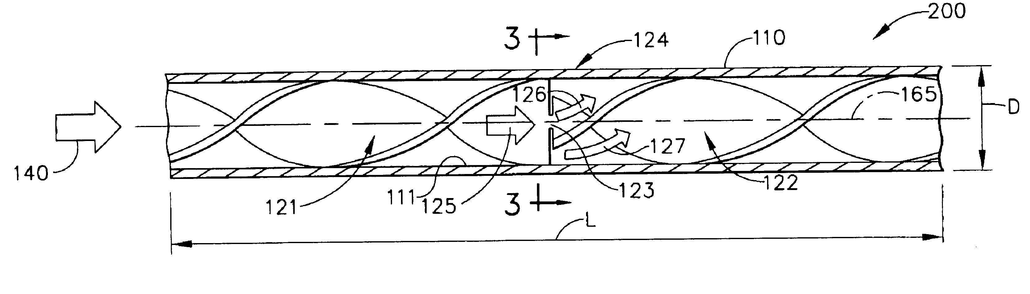
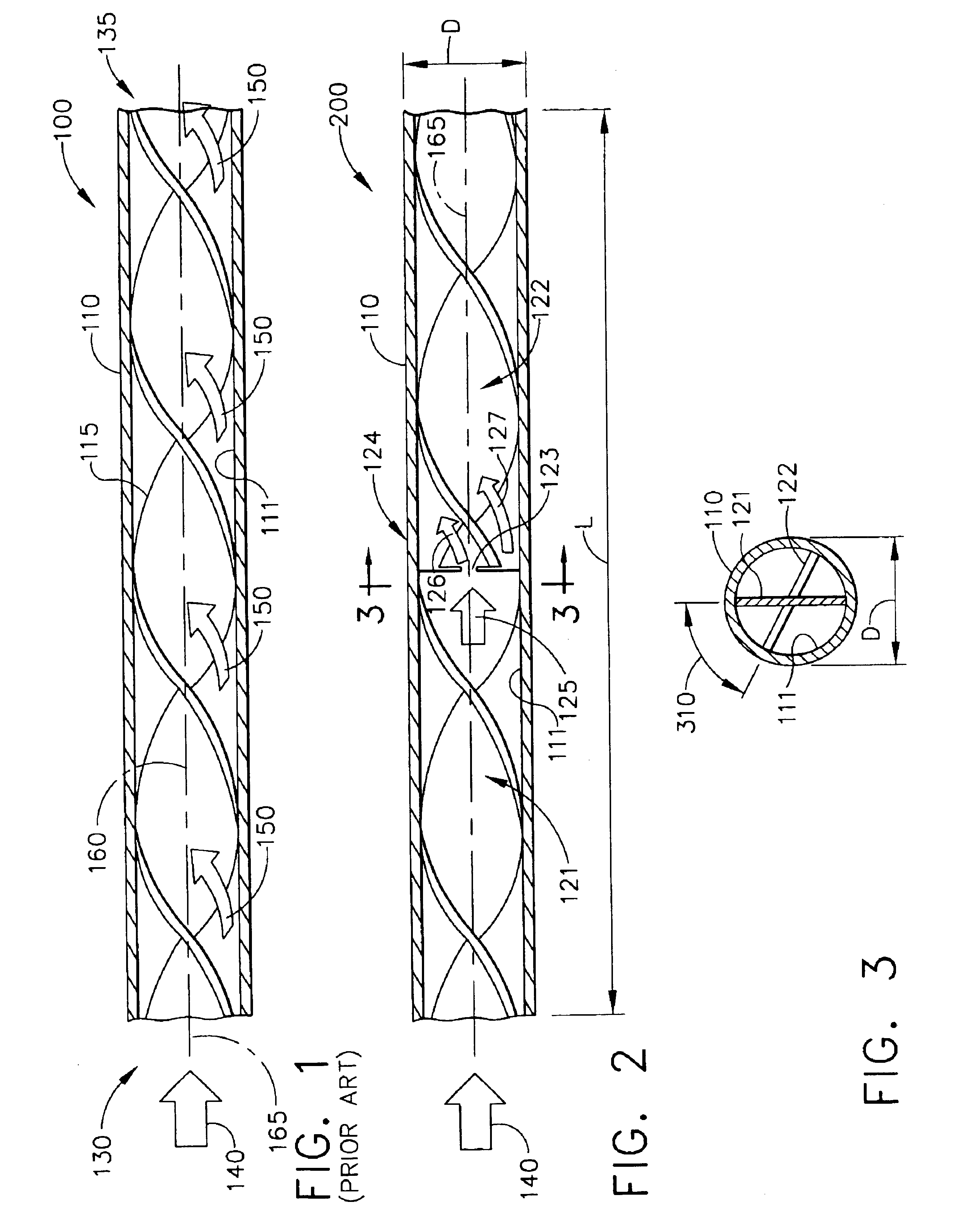
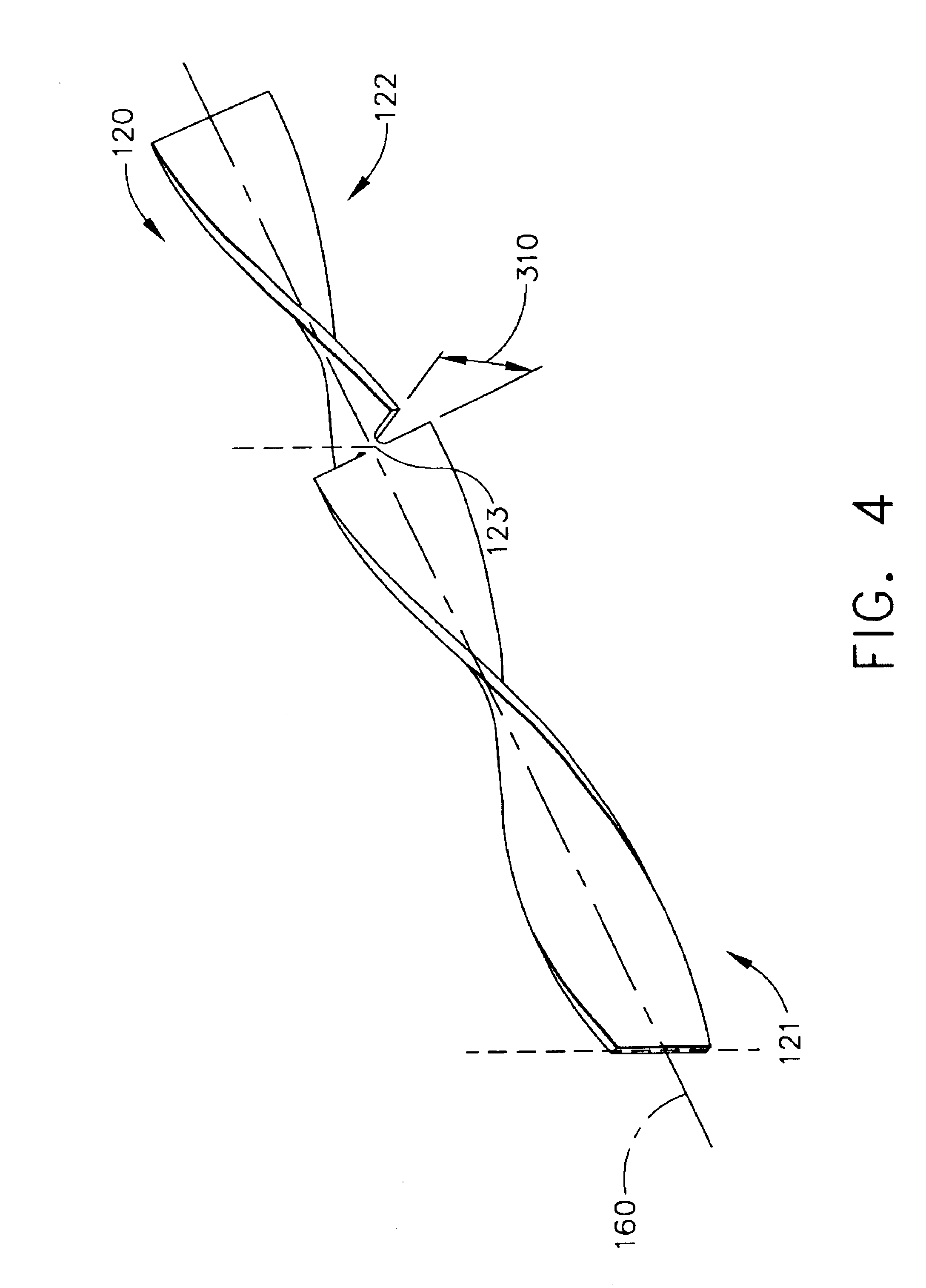
[0040]A segmented turbulator was made with a stainless steel strip with 0.2″ in width 12″ long and 0.0025″ thick. Eight segments each having a length of 1.5″ were formed. The twist angle a within each segment was 90° while the offset angle between segments was also 90°. The segmented turbulator was then inserted into a thin wall, stainless steel tube with length of 12″, to form Tube A according to one embodiment of the tube assembly. Separately, a similar tube was dimpled by axial compression to a depth of 0.04″ to form sets of two opposed dimples along the length of the tube. Eight sets of dimples were formed with linear separation of 1.5″ between adjacent sets, to form Tube B according to another embodiment of the tube assembly. Finally, another tube 12″ long and having no modification was used as a reference, to form Tube C. Tubes A, B, and C were washed by industrial detergent solution, followed by drying in ambient air.

EXAMPLE II

[0041]An Al2O3 slurry was made by mixing 15% Boeh...

example ii

Catalytic Ozone Destruction Test

[0042]Catalyzed tubes A, B, and C prepared according to Example II were mounted separately inside of the reactor of a test bed in which an air flow containing ozone with concentration of 2.4 ppm was directed towards the entry end of the catalyzed tubes. The flow rate was maintained at 14 standard liter / min while the reactor temperature was raised from ambient to 600° F. Simultaneously, the ozone concentrations upstream and downstream of the reactor were measured by using two ozone monitors. The level of conversion, calculated as the ozone concentration reduction at the exit ends of the tube assemblies over that of the respective entry ends, was seen as a function of the reactor temperature and plotted in graph 800 shown in FIG. 8. As can be seen in graph 800, the plot for Tube A 810 had the best ozone conversion efficiency (>90%) through the entire operating temperature range. The plot for tube B 820 had second best ozone conversion efficiency in the ...

example iv

[0043]The catalyst slurry was prepared by mixing 30 wt. % of Hopealite fine powder (Carulite 400, Carus Chemical Company), 40% SR 125 synthetic silicone resin (GE Silicones) balanced with toluene. The mixture was then ball milled for two hours before further dilution by additional toluene to form a slurry with viscosity of 40 centipose. The slurry was then used to washcoat the 12″ tubes with the same method used in Example II, followed by drying, curing and calcination at 400° C. for two hours in dry air flow. The ozone destruction efficiency of the tube at different temperatures was tested with the test bed described in Example III. The percentage of ozone conversion as a function of increasing temperature was plotted on graph 900 as shown in FIG. 9. Excellent conversion efficiency was observed.


PUM

PropertyMeasurementUnit
offset angleaaaaaaaaaa
temperatureaaaaaaaaaa

Abstract

A tube assembly for cooling an incoming fluid stream and destroying pollutants contained therein comprises a tube with a catalytic coating on its inner wall and an arrangement for disrupting laminar flow of the fluid stream as it transits the tube, thereby causing turbulence which increases mass transfer between the gas phase and the catalyst-coated inner surfaces. One embodiment comprises an axially inserted turbulator that is segmented by one or more axially directed cuts, each segment rotated by an offset angle with respect to an adjacent segment, and optionally coated with the catalytic coating. Another embodiment comprises sets of opposed dimples, each set separated from its adjacent set by a linear distance and an axial angle. Such tube assemblies may be advantageously employed in aircraft environmental control systems for conditioning cabin air.

Description

BACKGROUND OF THE INVENTION[0001]The present invention generally relates to air purification systems for use in aircraft and, in particular, to environmental control systems (ECS) for use on aircraft to remove pollutants from the ambient air for cabin usage.[0002]A commercial aircraft is generally equipped with an environmental control system (ECS) which provides fresh, conditioned air to the on-board passengers. A typical ECS receives compressed air, or bleed air, from an aircraft gas turbine engine and delivers it to the cabin. This bleed air after expansion has a temperature in the range of 200°-500° C. It is typically directed to a primary heat exchanger, or precooler, where it is further cooled to a temperature in the range of 100°-150° C. From the precooler, this warm bleed air is then sent to an air conditioner that performs a final cooling function and delivers fresh air to the aircraft cabin. A remediation system, such as a stand-alone catalytic converter, is usually interp...

Claims


Application Information

Patent Timeline
Patent Type & Authority Patents(United States)
IPC IPC(8): B01D53/86B01D53/88F28F13/12
CPCB01D53/8675B01D53/885F28F13/12B01D2257/106F28F2265/00B64D2013/0685
Inventor LIU, DI-JIAFOOR, BELINDA S.WINSTEAD, DANIEL R.
Owner HONEYWELL INT INC
Why Eureka
Try Eureka