
Process for the production of a high pressure vessel particularly for a space engine and vessel obtained therby

Inactive Publication Date: 2005-11-08
EADS LAUNCH VEHICLE
View PDF15 Cites 13 Cited by
  • Summary
  • Abstract
  • Description
  • Claims
  • Application Information

AI Technical Summary

Benefits of technology

[0038]to the method of polymerization of the composite which perm

Problems solved by technology

The production of vessels fulfilling these requirements is not simple and at present, the vessels are entirely metallic, or of composite material with an internal metallic skin which serves as a core and an external filamentary winding of resin-impregnated fibers.
On the other hand, such vessels have numerous drawbacks because their production is very sensitive.
Thus, the process of production consists in starting with a rough blank of considerable thickness which is forged, machining to reduce its thickness, which requires a very long time for machining, a high consumption of precious material of which a large part ends as machining scrap.
Such an equatorial welding by electronic bombarding is difficult and costly.
Also, a metallic framework of this type constitutes substantially half the cost of the final vessel.
On the other hand, changing material is not simple.
When searching among other metals or metallic alloys, one is always faced with a production process which remains complicated because there are hardly alternatives to forging and machining, at least for large vessels of the order of one meter in diameter.
Moreover, there can arise problems of compatibility with the gases, which leads to producers selecting titanium as the material, although it is of high cost.
On the other hand, if the plastic materials are known, it is also known that they are permeable to gases of high diffusivity such as helium and the amount of loss is prohibitive, in particular for operations of long duration such as satellites whose lifetime is often of the order of 10 to 15 years or even more.
Thus, in this case, not only the pressure decreases too much but the loses of gas can impair the environment of the satellite and particularly the onboard apparatus.
However, the vessel thus obtained does not permit the storage of gases of high diffusivity, such as helium, with an acceptable rate of loss for a storage of long duration.

Method used


Image

  • Process for the production of a high pressure vessel particularly for a space engine and vessel obtained therby
  • Process for the production of a high pressure vessel particularly for a space engine and vessel obtained therby

Examples


Embodiment Construction

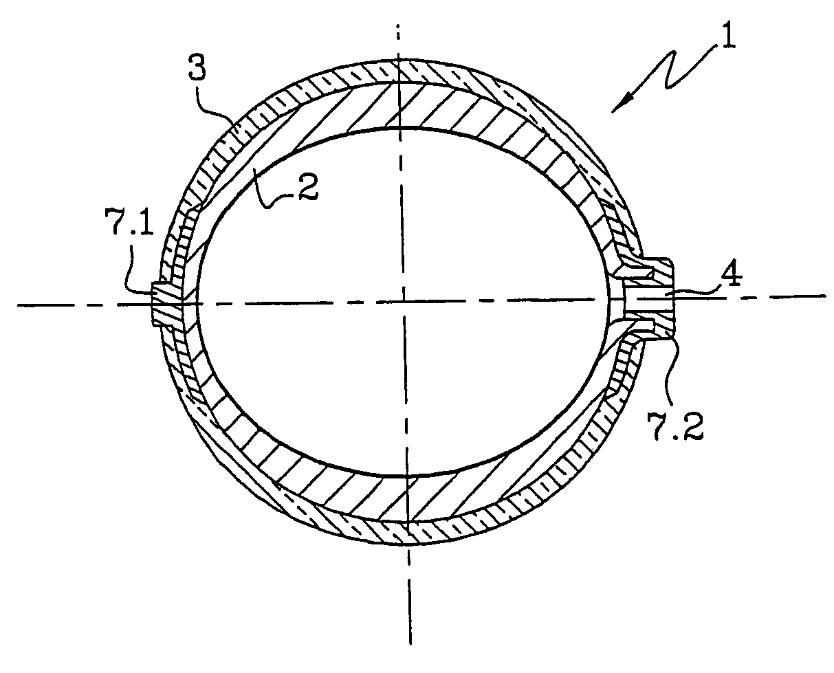
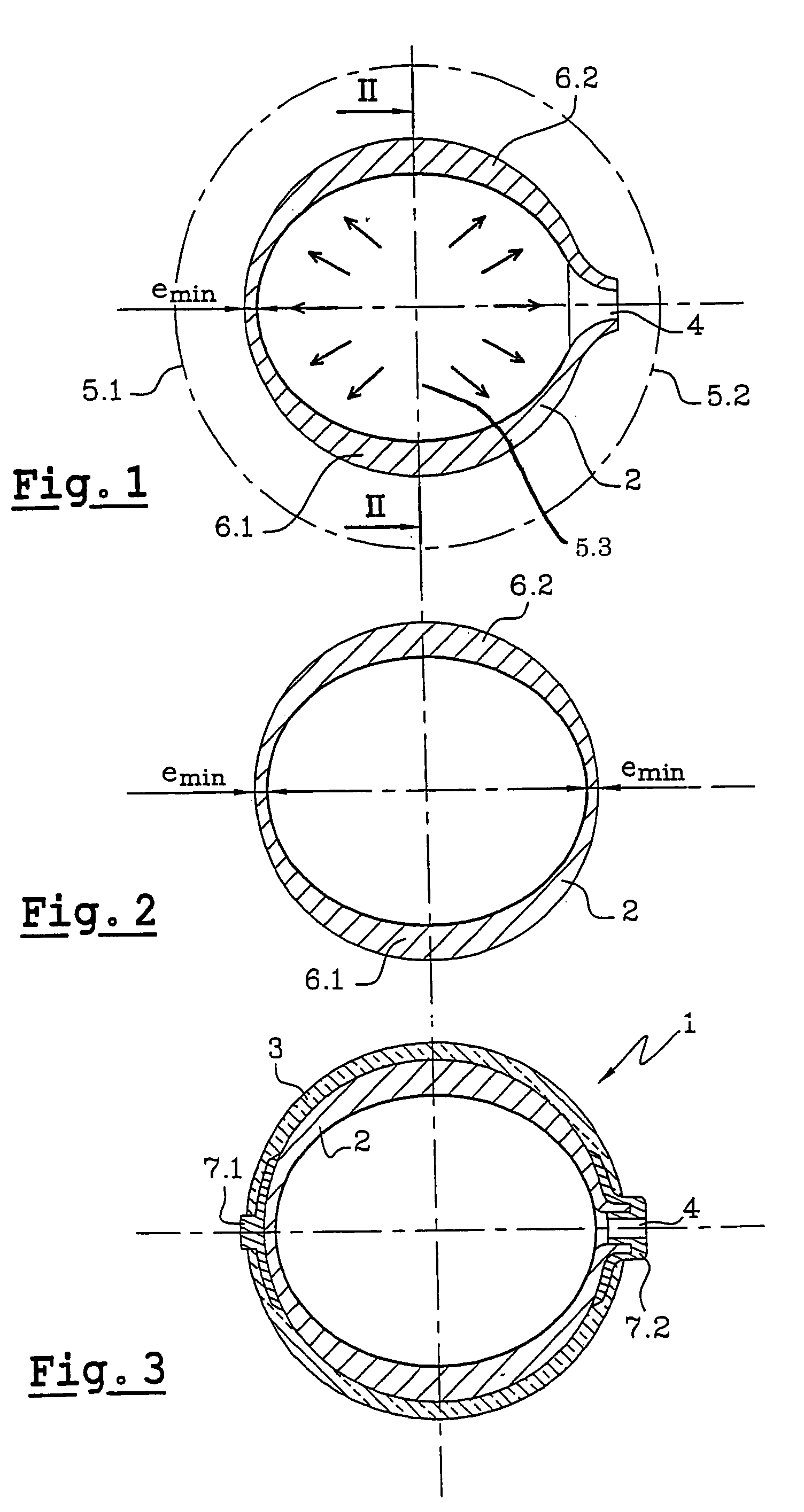
[0043]In FIG. 3, there is shown a vessel 1 according to the invention comprising an internal skin 2 clad with a winding of reinforcement 3 as well as an emptying and filling hole 4.

[0044]The process consists in producing a vessel with an internal skin of plastic material which has a mass at most equal to that of a vessel with an internal metallic skin, an acceptable rate of loss, below 5×10⁻⁹ Nm3 / s or a mean permeability of 1.16×10⁻¹³ Nm2 / bar / s.

[0045]The process therefore uses plastic materials which have a minimum of sites favorable to the passage of molecules of gas and more particularly of helium with very high diffusivity.

[0046]Also, the process consists in using polyethylene or crystallized polyamide which give the desired results.

[0047]There can be cited as a commercial product, semicrystallized polyamide PA6 of the type EMS Grillon R50HNZ.

[0048]Such a product has the following properties:[0049]density between 1.13 and 1.15,[0050]young's modulus comprised between 1 and 2 Gpa[0...


PUM

PropertyMeasurementUnit
Elongationaaaaaaaaaa
Thicknessaaaaaaaaaa
Pressureaaaaaaaaaa

Abstract

A process for the production of a vessel for high pressure gas, particularly helium, for a space launcher or for a satellite with a short lifetime, includes the steps of: a production of an internal skin of a plastic material selected from polyethylene and crystallized polyamide, a winding a reinforcement of fibers and resins, and a providing the obtained vessel with the necessary conduits and control valves.

Description

BACKGROUND OF THE INVENTION[0001]The present invention relates to vessels for high pressure gas used in space engines, launchers, satellites, probes, . . .[0002]Space launchers have vessels containing products adapted to be pressurized or emptied, such as fuels of the fusing type. To do this, there are used vessels of high pressure gas which permit carrying out the pressurization or emptying. This avoids mechanical systems and such arrangements permit very rapid actions, very precise and requiring control means based on electrovalves, which is less consumptive of energy and involves minimum added weight.[0003]The vector gas under pressure should have particular characteristic such as light weight, absence of risk of combustion. Because of this, helium is preferably used, particularly compared to hydrogen as to the absence of risk of explosion or fire.[0004]Nevertheless, for certain applications, nitrogen, oxygen or rare gases, neon, xenon can be envisaged.[0005]These vessels have a ...

Claims


Application Information

Patent Timeline
IPC IPC(8): F17C13/00F17C1/16F17C1/00B64G1/40B29C69/02B29C70/16B29D22/00B29K23/00B29K77/00B29K105/08B29L23/00F17C1/04
CPCF17C1/16F17C13/008F17C2203/066F17C2203/0663F17C2223/0123F17C2223/035F17C2270/0186Y02E60/321F17C2201/0128F17C2201/054F17C2203/012F17C2203/018F17C2203/0619F17C2203/0656F17C2203/0673F17C2203/0675F17C2209/2154F17C2221/012F17C2221/014F17C2221/017F17C2223/036F17C2260/011F17C2270/0194Y02E60/32
Inventor GAUTHIER, JACK
Owner EADS LAUNCH VEHICLE
Learn More