Multi-band arrayed waveguide grating with improved insertion loss and wavelength accuracy

a waveguide grating and wavelength accuracy technology, applied in multiplex communication, instruments, optical elements, etc., can solve the problems of increasing the number and complexity of bandwidth-intensive applications, requiring expensive up/down conversion of optical signals, and attracting much attention, so as to improve wavelength accuracy, improve the roll-off characteristics, and expand the free spectral range.

Inactive Publication Date: 2005-11-08
JDS UNIPHASE CORP
View PDF2 Cites 4 Cited by
  • Summary
  • Abstract
  • Description
  • Claims
  • Application Information

AI Technical Summary

Benefits of technology

[0023]By providing two periodic grating elements handling alternating bands, their free spectral range is allowed to expand, improving their roll-off characteristics. By providing separate inputs for each band, wavelength accuracy can be improved. Device flexibility can be further improved by using switch and interleaver fabrics at the inputs and outputs. The resultant device, generalized to handle any given band within a wavelength range, eliminates the need for separate component design and inventory tracking otherwise necessary.

Problems solved by technology

Fiber optic communication systems offer far greater capacity than their electrical counterparts (e.g., twisted pair, or coaxial cable) and are therefore attracting much attention as the number and complexity of bandwidth-intensive applications increase.
Digital time division multiplexing (TDM) of the data stream can be used to accommodate separate, independent data channels over the same wavelength band, but these systems require expensive up / down-conversion of the optical signal to an electrical version for multiplexing / demultiplexing the separate channels.
While providing some level of operational channelization, TDM techniques generally do not increase the overall data capacity of a single wavelength link.
However, the channel plan of certain communication systems of interest may offer opportunities to reduce the bandwidth of each mux / demux.
This approach, while offering good intra-band performance of each component (due to their narrower bandwidths), requires five separate components, adding to inventory cost and complexity.
Other types of OADM components, for example those based on thin film filters, suffer a similar disadvantage: each filter is designed for a specific wavelength and therefore separate components are needed for each band.

Method used


Image

  • Multi-band arrayed waveguide grating with improved insertion loss and wavelength accuracy
  • Multi-band arrayed waveguide grating with improved insertion loss and wavelength accuracy
  • Multi-band arrayed waveguide grating with improved insertion loss and wavelength accuracy

Examples


Embodiment Construction

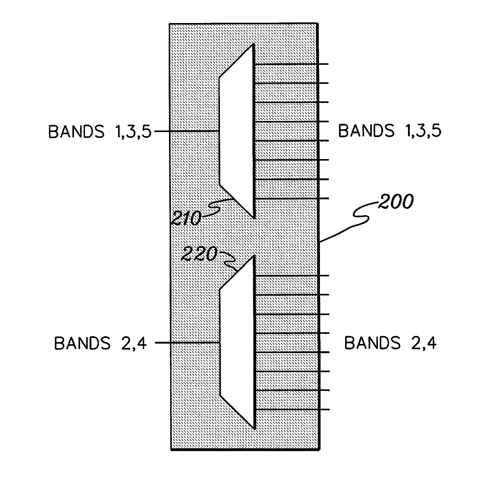
[0038]In accordance with the present invention, the periodic response of an AWG with a constrained free spectral range (FSR) is advantageously employed to use the same AWG to operate over more than one wavelength band of interest.

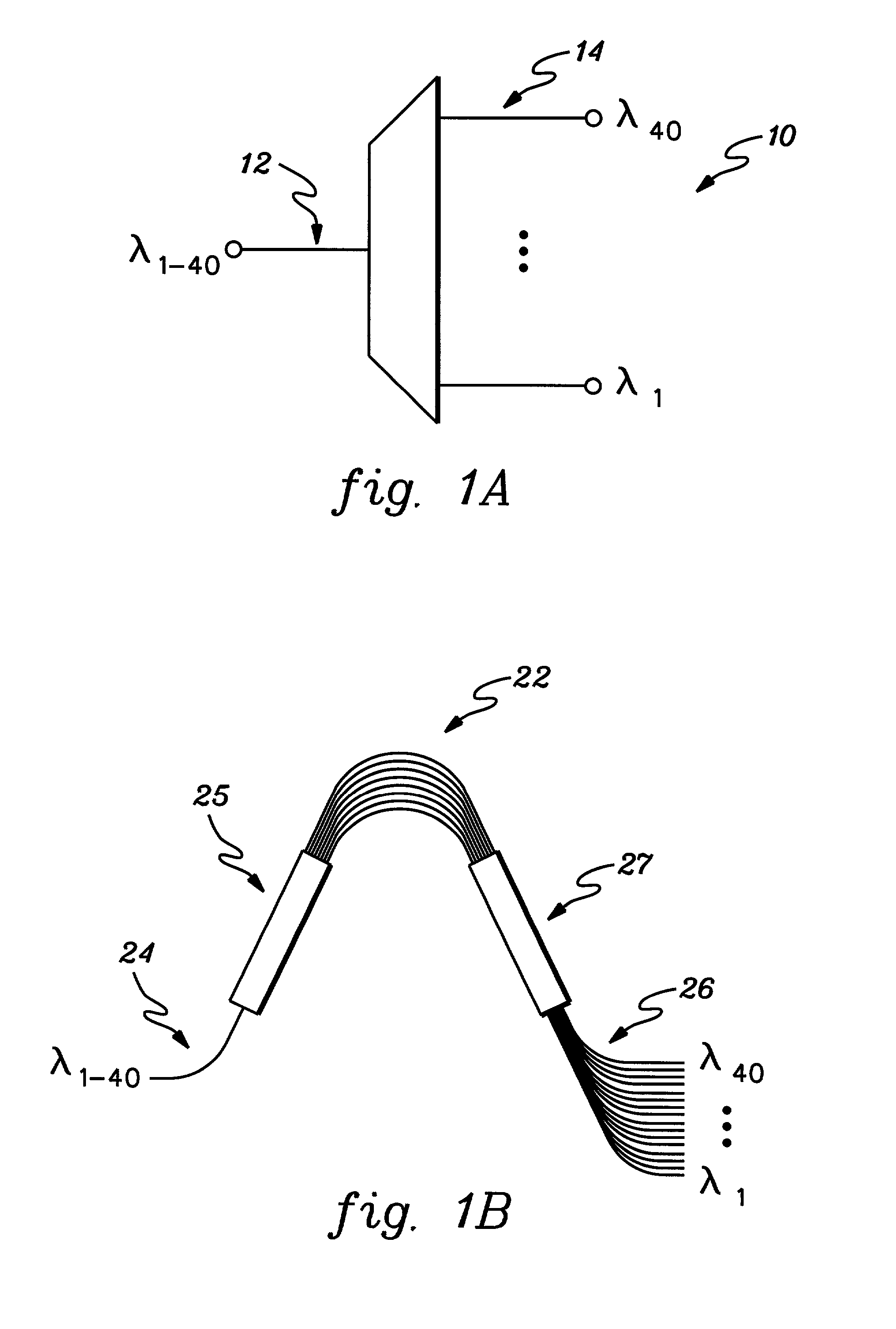
[0039]The FSR is modified in an AWG by changing the path length differences in the array waveguides 22 (FIG. 1b). The present invention extends to any type of AWG, including those described in the above-incorporated U.S. Patent Application entitled “Compact, Low Insertion Loss, High Yield Arrayed Waveguide Grating.”

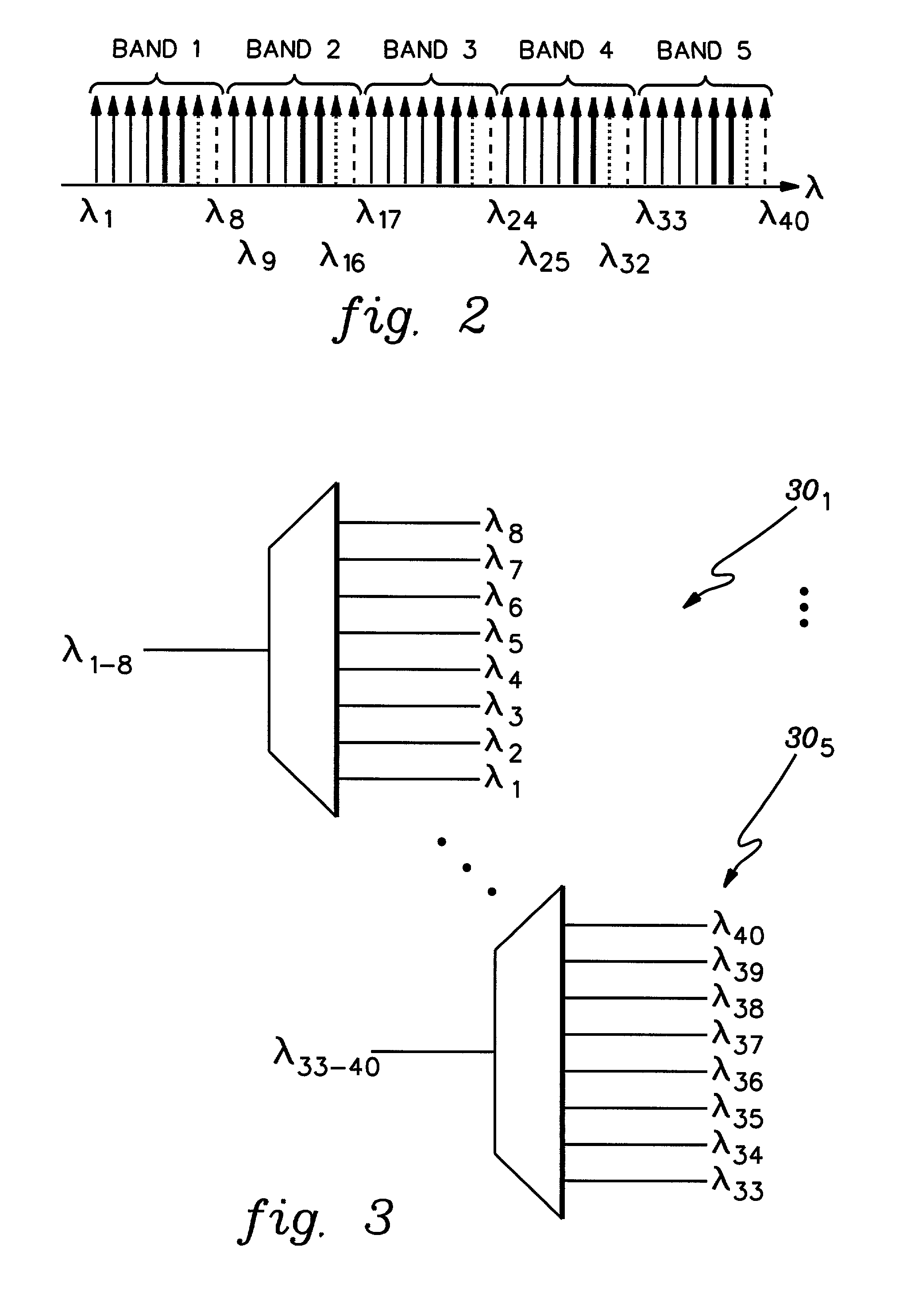
[0040]In one embodiment, the FSR is narrowed for a single AWG to 8 channels, corresponding to one of the 5 bands shown in FIG. 2. A single AWG can then be used for any of the 5 bands shown, since its response is periodic (period=8 channels or one band) across the entire 40 wavelength range. This is represented in FIG. 2 by the differing arrow types within each band; but similar across bands. If operated across the entire band, the same wavelength...


PUM


Abstract

A planar lightwave circuit generalized for handling any given band of multiple bands of a wavelength range, including a first grating element handling a first group of bands; and a second grating element handling a second group of bands. The first and second groups of bands overlap in the wavelength range, and may be spaced apart by a fixed wavelength value. By providing two periodic grating elements handling alternating bands, their free spectral range is allowed to expand, improving their roll-off characteristics. By providing separate inputs for each band, wavelength accuracy can be improved. Device flexibility can be further improved by using switch and interleaver fabrics at the inputs and outputs. The resultant device, generalized to handle any given band within a wavelength range, eliminates the need for separate component design and inventory tracking otherwise necessary.

Description

CROSS-REFERENCE TO RELATED APPLICATIONS[0001]This Application relates to the following copending, commonly assigned U.S. patent applications, each of which is incorporated by reference herein in its entirety:[0002]Ser. No. 09 / 901,474 entitled “Redundant Package for Optical Components” filed Jul. 9, 2001;[0003]Ser. No. 09 / 977,065 entitled “Waveguide Stress Engineering and Compatible Passivation in Planar Lightwave Circuits” filed Oct. 12, 2001;[0004]Ser. No. 10 / 010,931 entitled “High Thermal Efficiency, Small Form-Factor Packages Including Thermally Insulative Cavities, and Transfer Molded Variants” filed Nov. 20, 2001;[0005]Ser. No. 10 / 001,266 entitled “Precision Fiber Optic Alignment and Attachment Apparatus” filed Nov. 30, 2001; and[0006]Ser. No. 10 / 077,581 entitled “Compact, Low Insertion Loss, High Yield Arrayed Waveguide Grating” filed Feb. 15, 2002.FIELD OF THE INVENTION[0007]The present invention relates to planar lightwave circuits. More particularly, the present invention r...

Claims


Application Information

Patent Timeline
Patent Type & Authority Patents(United States)
IPC IPC(8): G02B6/35G02B6/34
CPCG02B6/12021G02B6/356
Inventor BHARDWAJ, JYOTIDOUGHERTY, DAVIDMURALI, VENKATESANYAMADA, HIROAKI
Owner JDS UNIPHASE CORP
Why Eureka
Try Eureka