
Miniature MEMS-based electro-mechanical safety and arming device

a technology of electro-mechanical safety and arming device, applied in the field of ultra-miniature electro-mechanical safety and arming, can solve the problems of large cost and volume, increased lethality or payload simultaneous demands, and inability to meet medium-and-small-caliber artillery, etc., and achieve the effect of reducing cost, size and power requirements, and simplifying and safety

Inactive Publication Date: 2005-11-15
US GOVT AS REPRSENTED BY THE SEC OF ARMY +1
View PDF10 Cites 70 Cited by
  • Summary
  • Abstract
  • Description
  • Claims
  • Application Information

AI Technical Summary

Benefits of technology

[0014]It is a primary object of the invention to function as the mechanical S&A for a 20-mm high-explosive air-burst (HEAB) gun-launched grenade. In this application, the invention reduces cost and volume significantly over the baseline system which is based on conventional fabrication techniques, i.e., not MEMS-based. Significantly, the present invention also has the potential for widespread application to other systems in the fuzing industry.
[0015]The present invention meets the need for an extremely miniature, low cost, electro-mechanical safety and arming device for small- and medium-caliber gun-launched and rifling-spun munition fuzes. It further meets the need for a safety and arming device incorporating a high degree of user safety and functional reliability. User safety means, among other things, the prevention of mechanical arming under all conditions except when the correct launch stimuli are received by the device as a result of gun launch. Reliability is the relative certainty that the device will perform its function when the correct launch stimuli are received by the device. The invention further meets the need for a miniature, low cost, electro-mechanical safety and arming device for small- and medium-caliber gun-launched and rifling-spun munition fuzes that can readily be mass-produced using advanced MEMS-based replication, assembly, explosive loading, and packing techniques for affordability.
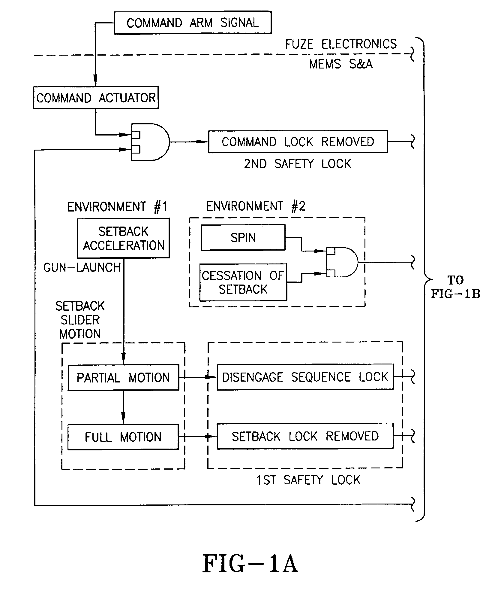
[0016]As compared to the prior art, the present invention reduces volume significantly over the non-MEMS S&A baseline; reduces cost over the non-MEMS S&A baseline; incorporates improved safety logic, with more locks and checks controlling the position of the arming slider than previous designs. The present invention also incorporates better design features, such as: 1) The working parts may, if desired, be fabricated all be of the same material, eliminating material incompatibility issues; 2) No lubrication is needed for MEMS assemblies, eliminating problems associated with aging lubricants found in prior-art mechanical S&As; 3) Fabrication methods based on semiconductor-industry mask, etch and release type technology implement more sophisticated mechanical safety logic and better fabrication and assembly methods.
[0018]Thus, the present invention provides the safety and arming function with a maximum of simplicity and safety and a minimum of cost, size, and power requirements.

Problems solved by technology

However, an ESA is currently not feasible for medium-and small-caliber artillery because of the relatively large cost and volume associated with components such as a slapper detonator and its high-voltage fireset, low-inductance fire circuit, a micro-controller or ASIC, a battery, and the need for one or more environment sensors as inputs to fuze logic.
In the munition fuzing industry the need for ‘smarter’ or more effective weapons often requires additional space within the weapon for signal and guidance electronics, power management, and sensors, while the need for greater lethality or payload makes simultaneous demands on volume.
The old methods of design, prototyping, and production involve S&A designs that are not optimal for integration with small- and medium-caliber munition fuzes.
The old methods are too bulky, too expensive to manufacture, do not achieve a sufficient amount of safety, are limited in reliability, or are difficult or unsuitable to integrate with current sophisticated fuze technology that incorporates advanced target proximity detection, sensor integration, guidance, and global positioning system data integration.
The old methods are similarly not optimal for large-caliber fuze applications, and for many of the same reasons.
In general, prior-art mechanical S&As that are fabricated using conventional (non-MEMS-based) manufacturing processes are too large; are too expensive; use too many parts, often of dissimilar materials, that must be assembled; involve a domestic precision small-parts manufacturing industry that is shrinking and moving overseas;involve tight clearances and dimensional tolerances that are expensive to fabricate and assure using conventional machining operations; involve materials and parts that require lubrication to reduce working friction, however, such lubricant can, over time, lose its lubricity, foul other parts, or become viscous; do not take advantage of recent micro-scale fabrication technologies that use principles and processes well known and widely utilized in the micro-electronic fabrication industry, e.g., optical masking directly from CAD layouts, optical exposure, chemical developing and rinsing, material plating or deposition, etc., to create three-dimensional mechanical structures.

Method used


Image

  • Miniature MEMS-based electro-mechanical safety and arming device
  • Miniature MEMS-based electro-mechanical safety and arming device
  • Miniature MEMS-based electro-mechanical safety and arming device

Examples


second embodiment

[0133]Description of a Second Embodiment

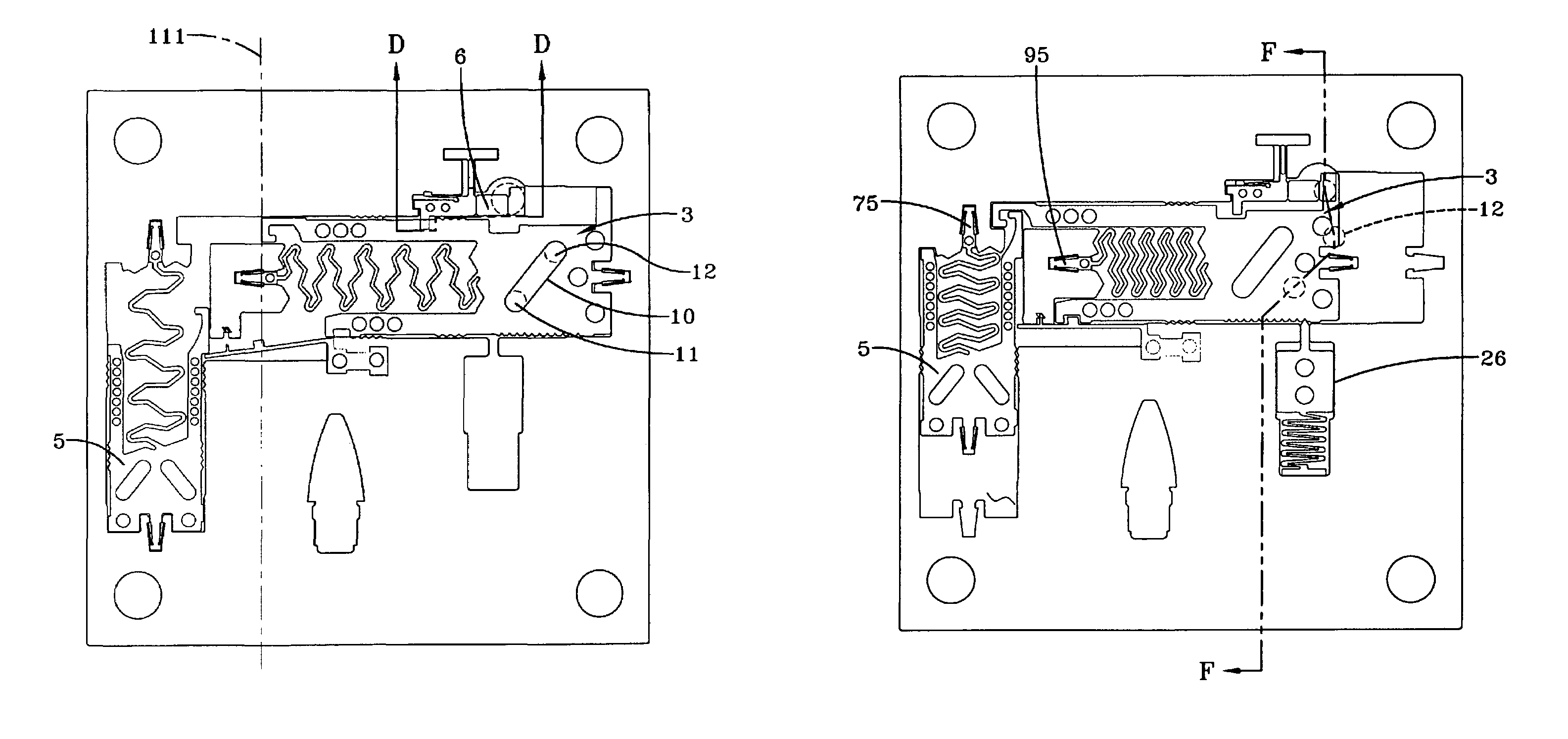
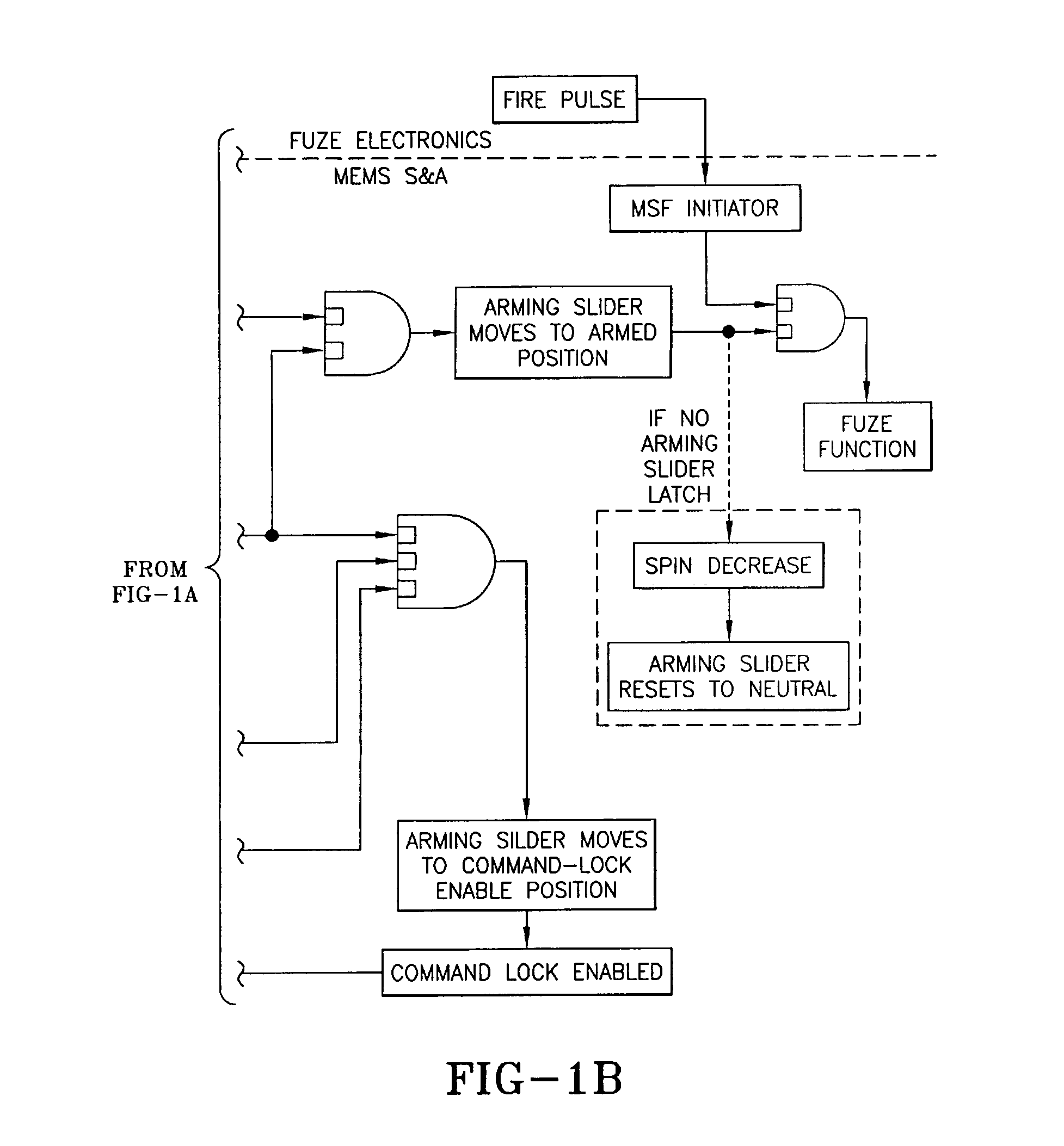
[0134]A second embodiment of the invention is the same as the first embodiment as shown in FIG. 2A except that the end-of-travel arming slider latch head 36 and latch socket 25 are omitted. This omission has the effect that if the spin decays before the munition is functioned by the fuze, the arming slider 3 will be retracted to the safe (explosives out of line) position by the arming slider bias spring 9. This feature is indicated by the dotted line and box titled “If No Arming Slider Latch” in the block diagram of FIG. 1B.

third embodiment

[0135]Description of a Third Embodiment

embodiment 148

[0136]FIG. 21 shows a plan view of a reverse-bias S&A device for a non-spin munition launch. A third preferred embodiment 148 for non-spin munitions shown in FIG. 21 comprises an assembly similar to that of FIG. 2A but with a different arming slider 112. In arming slider 112 the location of the transfer charge pocket 149 and its associated input column 113 and output column 126 has been changed to accommodate a reverse-bias spring 114. Reverse-bias spring 114 is tensioned by extending its latch head 114a into reverse-bias spring latch head socket 115. Arming slider 112 includes arming slider latch 117 and arming slider latch socket 116.

[0137]This third embodiment 118 functions as a miniature MEMS-based electro-mechanical S&A for gun-launched munitions that are not spin stabilized. Munitions without spin stabilization lack a significant centrifugal acceleration-induced spin component to drive the arming slider 112 toward the armed position, so a spring force is substituted by this de...


PUM


Abstract

A MEMS type safety and arming device includes a substrate; a frame disposed on the substrate; a setback slider disposed in the frame, the setback slider moving linearly in response to a setback acceleration; an arming slider disposed in the frame, the arming slider moving linearly in an arming direction perpendicular to the direction of the setback acceleration and in response to spin; a setback lock lever disposed in the frame, the setback lock lever engaging the arming slider to prevent linear motion of the arming slider until the setback slider contacts and moves the setback lock lever; and a command lock rocker disposed in the frame, the command lock rocker engaging the arming slider to prevent full arming motion of the arming slider until after the command lock rocker is actuated.

Description

CROSS REFERENCE TO RELATED APPLICATIONS[0001]This application claims the benefit of priority of U.S. provisional patent application Ser. No. 60 / 319,727 filed on Nov. 25, 2002, which application is expressly incorporated by reference.FEDERAL RESEARCH STATEMENT[0002][The inventions described herein may be manufactured, used and licensed by or for the U.S. Government for U.S. Government purposes.]BACKGROUND OF INVENTION[0003]The invention relates to an ultra-miniature electro-mechanical safety and arming (S&A) device for gun-launched munitions. The invention incorporates mechanical logic for reliability and safety. The invention is typically fabricated using micro-electromechanical systems (MEMS) based technology and processes, but can also be fabricated or assembled using offshoot technologies such as plating, molding, plastic injection, ceramic casting, etc. An important application of the invention is in munition fuze safety and arming for gun-launched munitions, wherein launch (set...

Claims


Application Information

Patent Timeline
IPC IPC(8): F42C15/00F42C15/26
CPCF42C15/26
Inventor ROBINSON, CHARLES H.WOOD, ROBERT H.HOANG, THINH Q.
Owner US GOVT AS REPRSENTED BY THE SEC OF ARMY
Features
  • Generate Ideas
  • Intellectual Property
  • Life Sciences
  • Materials
  • Tech Scout
  • Unparalleled Data Quality
  • Higher Quality Content
  • 60% Fewer Hallucinations
Learn More