Photovoltaic power generating apparatus, method of producing same and photovoltaic power generating system

a photovoltaic power generation and photovoltaic technology, applied in the direction of machines/engines, propulsion parts, process and machine control, etc., can solve the problems of increasing the non-power generation area not used for power generation in reducing the efficiency of area power generation of the solar cell module, and taking time and trouble. , to achieve the effect of reducing the influence of partial shadows and reducing production costs

Inactive Publication Date: 2005-11-22
CANON KK
View PDF34 Cites 220 Cited by
  • Summary
  • Abstract
  • Description
  • Claims
  • Application Information

AI Technical Summary

Benefits of technology

[0021]The present invention has been implemented taking into account the above described circumstances and it is an object of the present invention to provide a photovoltaic power generating apparatus of a simple configuration capable of reducing a production cost, reducing influences of partial shadows and variations in its characteristics, a photovoltaic power generating system using the photovoltaic power generating apparatus and a method of producing the photovoltaic power generating apparatus.

Problems solved by technology

Especially when a solar cell module having a large area is produced, the step of serially connecting many solar cell elements takes time and trouble, which constitutes a serious problem in producing a solar cell module having a large area.
Furthermore, a configuration of a plurality of solar cell elements serially connected using a wiring member such as an inter-connector requires a gap to insert the inter-connector between solar cell elements, the number of such gaps increases as the number of serially connected solar cell elements increases, which entails an increase in the non-power generation area not used for power generation in the solar cell module.
As a result, the efficiency of area power generation of the solar cell module is reduced.
For example, if one of the serially connected solar cell elements is covered with a partial shadow, the current generated from the cell is reduced and the rates of currents generated from other cells are also limited by this cell.
However, even using this method cannot completely eliminate the influences of the partial shadow on other power generating cells.
H08-70533, providing an inverter for each solar cell element may alleviate work in the serial connection step which is the above described problem, but this requires a cutting step and an etching step at the ends of individual solar cell elements when creating those solar cell elements, which still takes time and trouble.
Furthermore, when a structure of mounting solar cell elements on a support is adopted, it is necessary to precisely locate those solar cell elements at certain intervals to improve electric insulation between the respective solar cell elements, the external appearance and efficiency of area power generation, which is however a difficult task and constitutes a factor responsible for a cost increase.
However, in such a configuration, the value of the current flowing through the current collection bus bar is the sum of the plurality of output currents of the solar cell elements, causing another problem that as the number of solar cell elements increases and the area of the solar cell module increases, loss in current collection also increases considerably.
To solve the problem of this current collection loss, the cross section of the current collection bus bar may be increased, but this solution causes the weight and volume of the current collection bus bar to grow considerably, making the producing / transporting work difficult.

Method used


Image

  • Photovoltaic power generating apparatus, method of producing same and photovoltaic power generating system
  • Photovoltaic power generating apparatus, method of producing same and photovoltaic power generating system
  • Photovoltaic power generating apparatus, method of producing same and photovoltaic power generating system

Examples


first embodiment

(First Embodiment)

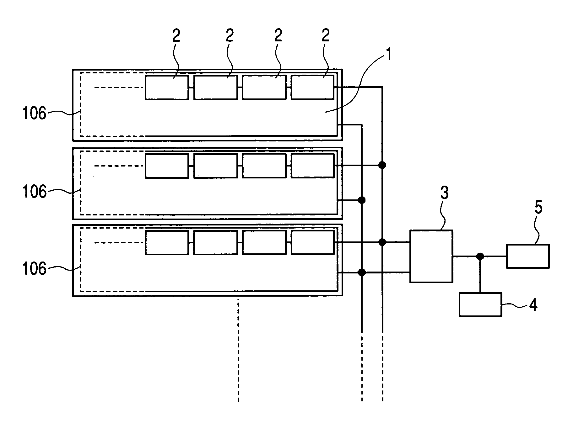
[0077]FIG. 1 is a schematic view showing a configuration of a photovoltaic power generating system according to a first embodiment of the present invention. Reference numeral 1 denotes a single solar cell element formed on a conductive substrate, 2 denotes a DC-DC converter, 3 denotes an inverter, 4 denotes a load and 5 denotes a commercial system.

[0078]The term “solar cell element” used herein refers to a minimum unit having the function as a solar cell capable of extracting electric power. For example, when a power generation area is segmented by etching lines, the solar cell element refers to a certain area having a photovoltaic layer segmented by etching lines, etc., which is a minimum unit having the function as a solar cell capable of extracting electric power therefrom. The solar cell element is not limited to one having a single photoelectric conversion layer and may also have a plurality of photoelectric conversion layers stacked one upon another. Examples...

second embodiment

(Second Embodiment)

[0187]A second embodiment of the photovoltaic power generating system according to the present invention will be explained below. Explanations of the same parts as those of the first embodiment will be omitted and characteristic parts of this embodiment will be principally explained below.

[0188]FIG. 10 is an external view showing a schematic configuration of the second embodiment and FIG. 11 is an equivalent circuit diagram of the second embodiment.

[0189]As a solar cell element 1 of this embodiment, substantially the same one as that of the first embodiment is used and detailed explanations thereof will be omitted.

[0190]FIG. 12 is an enlarged view of a connection portion between the solar cell element 1 and DC-DC converter 2 of this embodiment. Here, the position in the solar cell element at which the DC-DC converter 2 is attached is the same as that of the first embodiment, but the second embodiment is different in that an output terminal 59 is drawn out of the e...

third embodiment

(Third Embodiment)

[0203]A third embodiment of the photovoltaic power generating system according to the present invention will be explained below. Explanations of the same parts as those of the first embodiment and second embodiment will be omitted and characteristic parts of this embodiment will be principally explained below.

[0204]A solar cell element used in this embodiment has substantially the same configuration as that used in the first embodiment, but it is different only in a stacked configuration of the semiconductor layer.

[0205]More specifically, on a roll-shaped, cleaned, long stainless steel substrate of 0.1 mm thick as a conductive substrate, a layer of Al containing 1% of Si was formed using a sputtering method in a film thickness of 5,000 Å as a lower electrode layer. Then, an n / i / p-type amorphous silicon semiconductor layer was formed using B2H6, SiH4 and H2 gases for a p-type semiconductor, SiH4 and H2 gases for an i-type semiconductor and PH3, SiH4 and H2 gases for...


PUM


Abstract

A photovoltaic power generating apparatus is provided which comprises a single solar cell element formed on a substrate and a plurality of power conversion devices individually connected to the solar cell element for converting an output of the solar cell element.

Description

BACKGROUND OF THE INVENTION[0001]1. Field of the Invention[0002]The present invention relates to a photovoltaic power generating apparatus, photovoltaic power generating system and method of producing the photovoltaic power generating apparatus.[0003]2. Related Background Art[0004]In recent years, with the emergence of serious problems such as global warming due to emission of carbon dioxide, etc., caused by use of fossil fuel and pollution with radioactivity by accidents at atomic power plants and nuclear waste, there is a glowing concern about global environment and energy. Under such circumstances, solar photovoltaic power generation using solar radiation, geothermal power generation using geothermal power and wind power generation using wind power, etc., are being put to practical use worldwide as inexhaustible and clean energy sources.[0005]Of these energy sources, there are various modes of solar photovoltaic power generation using a solar cell according to an output scale fro...

Claims


Application Information

Patent Timeline
Patent Type & Authority Patents(United States)
IPC IPC(8): B60K16/00F03G6/00G05F1/66G05F1/67H02M7/42H01L31/042H02J7/35H02M3/00H01L31/04H02J3/38H01L27/142
CPCH01L27/142H01L31/042H01L31/02021H02J3/383Y02E10/46Y02E10/563H02M7/4807H01L31/0201H01L31/03921H01L31/048H01L31/046H02S40/32H02S20/26Y02B10/10H02S40/36H02J2300/24H02J3/381Y02E10/56H02J7/35
Inventor TOYOMURA, FUMITAKAMIMURA, TOSHIHIKO
Owner CANON KK
Why Eureka
Try Eureka